Laser burn through sensor

a sensor and laser technology, applied in the field of laser burn through sensor, can solve the problems of high radiation exposure level, damage to anything along unwanted optical path, and high risk, and achieve the effect of reducing the need for alignment of optical detectors

Inactive Publication Date: 2005-12-22
NORTHROP GRUMMAN CORP
View PDF25 Cites 10 Cited by
  • Summary
  • Abstract
  • Description
  • Claims
  • Application Information

AI Technical Summary

Benefits of technology

[0007] Preferably, the optical laser burn through sensor further comprises a light diffuser, positioned near the optical detector to reduce the need for alignment of the optical detector with laser ligh

Problems solved by technology

There is always some level of risk that optical components exposed to high levels of radiation will break down, allowing laser radiation to “burn through” a component, and then inflict damage on anything along an unwanted optical path.
Without early detection of laser burn through, there is a significant risk of damage to property, as well as serious, and possibly fatal, injury to nearby personnel.
Unfortunately, thermal sensors of this and similar types have a relatively slow response time.
Thermal detection inherently involves a delay during which the radiation being detected raises the temperature of the detector and its surround

Method used


Image

  • Laser burn through sensor
  • Laser burn through sensor
  • Laser burn through sensor

Examples


Embodiment Construction

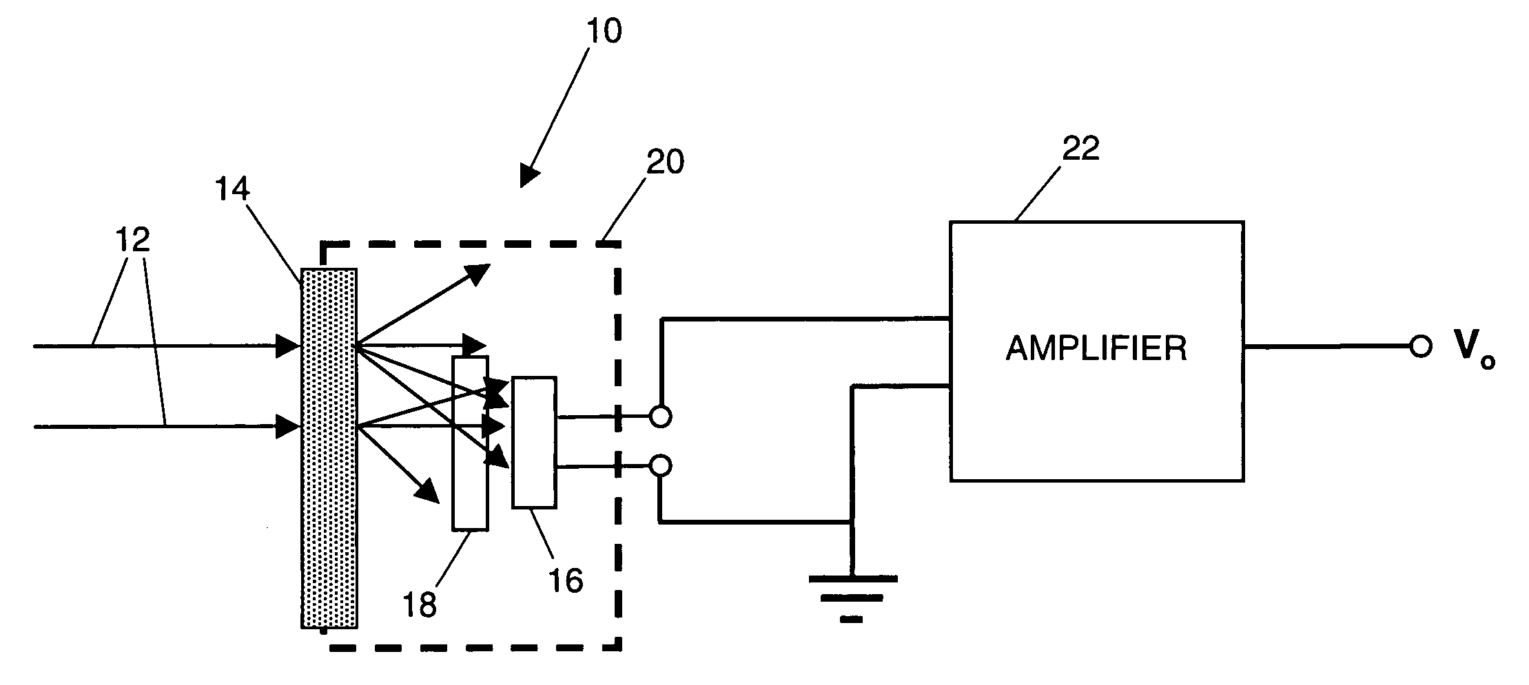
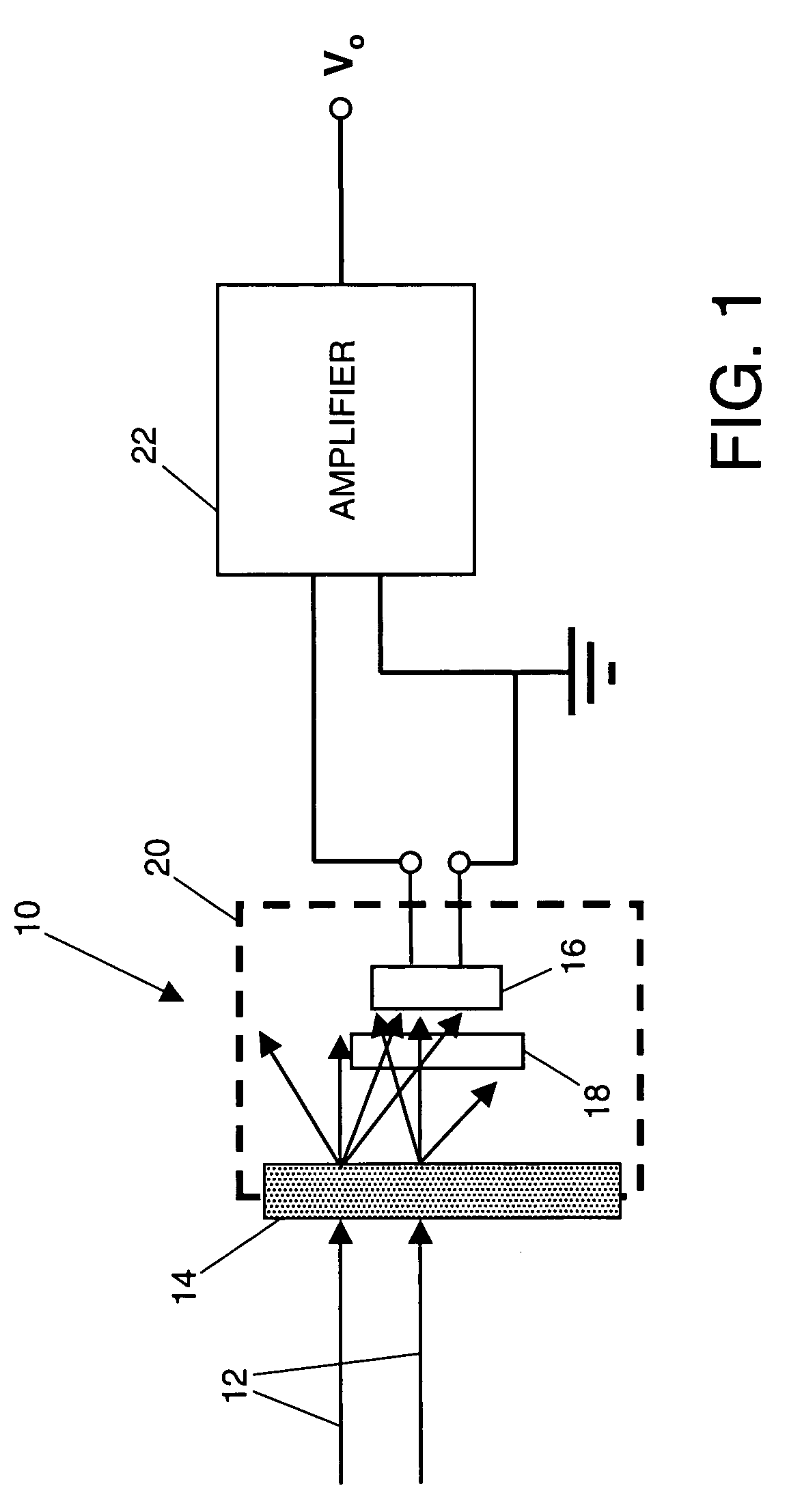
[0017] As shown in the drawings for purposes of illustration, the present invention pertains to a protective device for sensing laser burn through of an optical component. As discussed above, high energy laser equipment poses a serious risk of damage to equipment and personnel unless means are provided for sensing any deviation of laser radiation from its intended optical path. Thermal sensors of the prior art are inherently slow to react to laser burn through and may also be sensitive to heat radiated from other sources.

[0018] In accordance with the invention, one or more optical detectors are employed to detect the presence of laser radiation in locations where there should be none. Use of an optical detector significantly reduces the reaction time of the sensor, relative to one of the thermal type, and therefore significantly reduces the risk of damage from an errant laser beam that has burned through an optical component.

[0019]FIG. 1 illustrates the principle of the present in...


PUM

PropertyMeasurementUnit
Temperatureaaaaaaaaaa
Poweraaaaaaaaaa
Energyaaaaaaaaaa

Abstract

An optical sensor for detecting the presence of laser radiation in locations outside an intended optical path in a high energy laser device. An optical sensor, such as a photodiode, is positioned to receive light through an optical component when it fails to operate properly and laser light burns through the component. The optical sensor preferably includes a diffuser, an optical filter, and electrical circuitry to compare the signal generated by the photodiode with a selected reference signal, and to use the photodiode signal to actuate an alarm indicator and to disable power to the laser source. A thermal detector may be employed as a backup detection device.

Description

[0001] This invention was made with Government support under Contract No. F29601-03-C-0061 awarded by the U.S. Air Force. The Government has certain rights in this invention.BACKGROUND OF THE INVENTION [0002] This invention relates generally to optical systems for high energy lasers and, more particularly, to protective devices for sensing any unwanted deviation of laser radiation from its intended optical path. High energy lasers have many commercial and military applications. Commercial uses include welding and cutting operations. Military uses include missile defense, including directed energy systems based either at fixed locations on the ground or in moving vehicles on or above ground. All such applications have in common the need to confine a high energy laser beam to a designated optical path, using mirrors or other optical components. There is always some level of risk that optical components exposed to high levels of radiation will break down, allowing laser radiation to “b...

Claims


Application Information

Patent Timeline
IPC IPC(8): B23K26/00B23K26/42F16M11/06
CPCB23K26/422B23K26/702
Inventor ARENBERG, JONATHAN W.SUN, ALLEN S.KOMINE, HIROSHISOULE, MATTHEW W.
Owner NORTHROP GRUMMAN CORP
Why Eureka
Try Eureka