Infrared thermometer with through-the-lens visible targeting system

a visible targeting and infrared thermometer technology, applied in the field of optical detectors, can solve the problems of inability to visually control the alignment of the irt with the target, the irt is known to be extremely susceptible to reading errors, and the output reading is erroneous, so as to achieve cost-effective and mass-producible implementation

Inactive Publication Date: 2005-12-22
EVEREST CHARLES E
View PDF3 Cites 16 Cited by
  • Summary
  • Abstract
  • Description
  • Claims
  • Application Information

AI Technical Summary

Benefits of technology

[0010] The invention consists of combining a conventional IR thermometer with a visible light source (VLS) having exactly the same size and shape as the IR detector and used to illuminate the target surface so as to visibly identify the area to be measured. The VLS is judiciously positioned within the system so that its visible image, formed by the optics of the IRT system on the surface of the target, precisely corresponds to the area of the target the temperature of which is being measured. As a result, should the VLS image fall outside of the target surface, the IRT system can be appropriately aligned visually to provide for the exact temperature measurement of the target area.
[0011] According to one aspect of the invention, a visible light source (VLS) having a surface exactly the same in size and shape as the surface of a preferably lambertian IR detector is incorporated into a conventional IRT system and positioned so as to make the images of the IR detector and the VLS formed by the achromatic optics of the IRT system coincide on the surface of the target. This is preferably achieved by placing the VLS and the IR detector symmetrically with respect to a dichroic beamsplitter on the optical axis of the IRT. As a result, the surface area illuminated with the VLS on the target is the same area of the IR image of the detector formed on the target. Being coincident with the image of the detector, the image of the VLS on the target surface precisely and visibly defines the area of the target being imaged and measured by the detector. This allows for the accurate visible re-alignment of the IRT system should the measurements require it. It is understood that the symmetrical placement of the VLS and the IR detector with respect to the beamsplitter is not strictly required, so long as their images remain coincident.
[0012] According to another aspect of the invention, the exact location and dimensions of the target area under test are precisely identified, not only under static but also under variable imaging conditions (such as re-focusing of the IRT lens). This is achieved by forming an identifiable pattern on the surface of the VLS which comes into visible focus on the target when focusing of the IRT optics is optimal. For example, the VLS pattern can resemble the electron collector pattern of the IR detector. As a result of such precise focusing-identification feature, the system can perform errorless measurements of targets located at variable distances from the IRT or, alternatively, it can measure the same target with variable spatial resolution.
[0013] Since practical considerations often dictate miniaturization of test equipment, the preferred embodiment of the thermometer of the invention utilizes a single optical system to perform both optical functions of the system; that is, to identify the target area to be measured and to collect the IR radiation from that area onto the detector. This is achieved by operating the achromatic optics of the IRT in a two-directional dichroic imaging regime, wherein the VLS image is projected onto the target surface in visible light in one direction and the IR light emanating from the area of that image is delivered to the IR detector in the opposite direction by the same set of optics. Thus, the invention allows for cost-effective and mass-producible implementation of a variable-focus measurement-error-free IRT system with a through-the-lens target-identification feature.

Problems solved by technology

IRTs are known to be extremely susceptible to reading errors resulting from improper alignment with the target.
Since the background to any target under test emits a certain amount of IR radiation, when the IRT's optical system is not pointing directly at the target, the detector collects energy coming from not only the target but also from background, thereby providing an erroneous output reading.
This shortcoming of conventional IRTs is augmented by the fact that IRTs operate in the portion of light spectrum not visible to the human eye (typically at wavelengths longer than 2 μm) and, therefore, the alignment of the IRT with the target cannot be visually controlled.
Therefore, the output reading of the IR detector that is specifically calibrated to measure the temperature of the surface of the target Twill contain an error.
This problem persists regardless of the imaging conditions provided by the optical system L of the IRT.
For example, if a zoom lens is used, a reading error will be present for any focal setting of the lens as long as the area MA imaged onto the detector D does not completely fall within the perimeter of the target T. As is well understood in the art, additional reading errors may also be introduced when the target area under test is tilted with respect to the optical axis of the IRT system.
This solution does not solve the major problem, however.

Method used


Image

  • Infrared thermometer with through-the-lens visible targeting system
  • Infrared thermometer with through-the-lens visible targeting system
  • Infrared thermometer with through-the-lens visible targeting system

Examples


Embodiment Construction

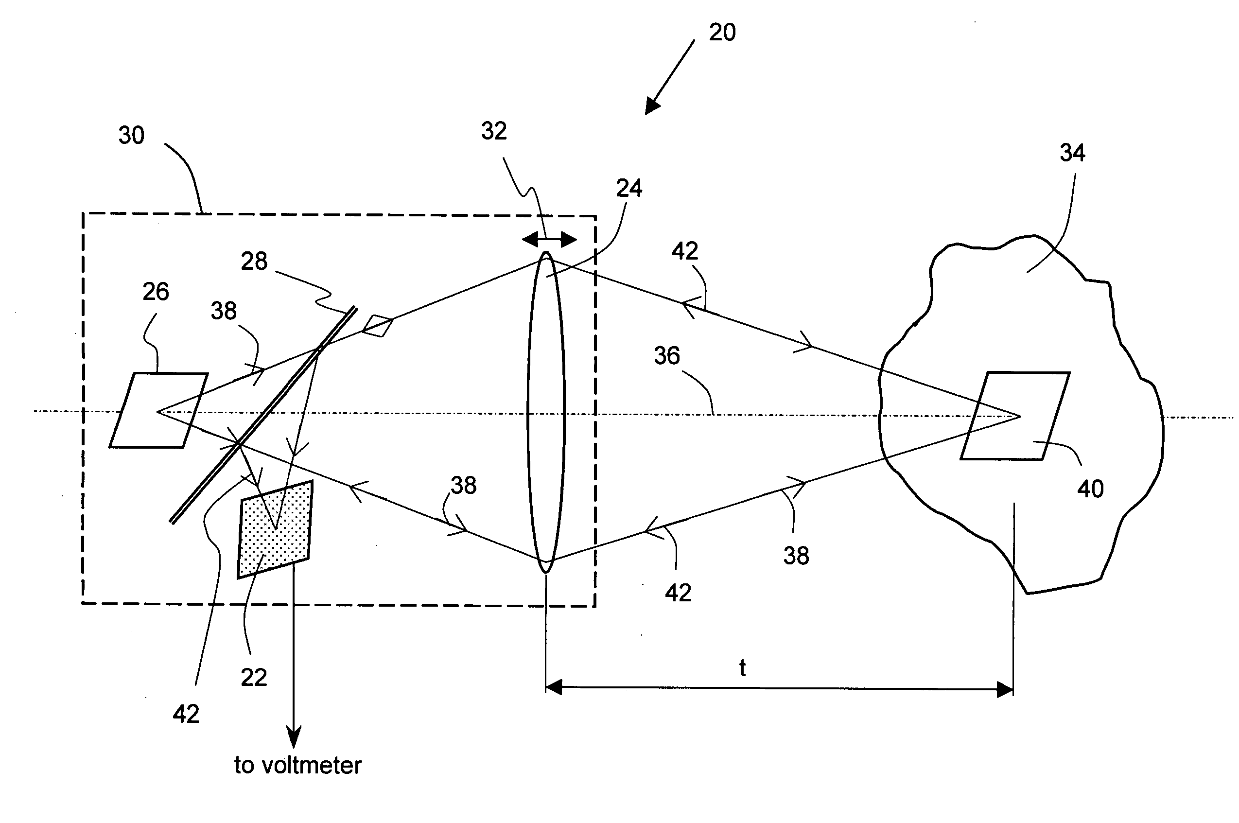
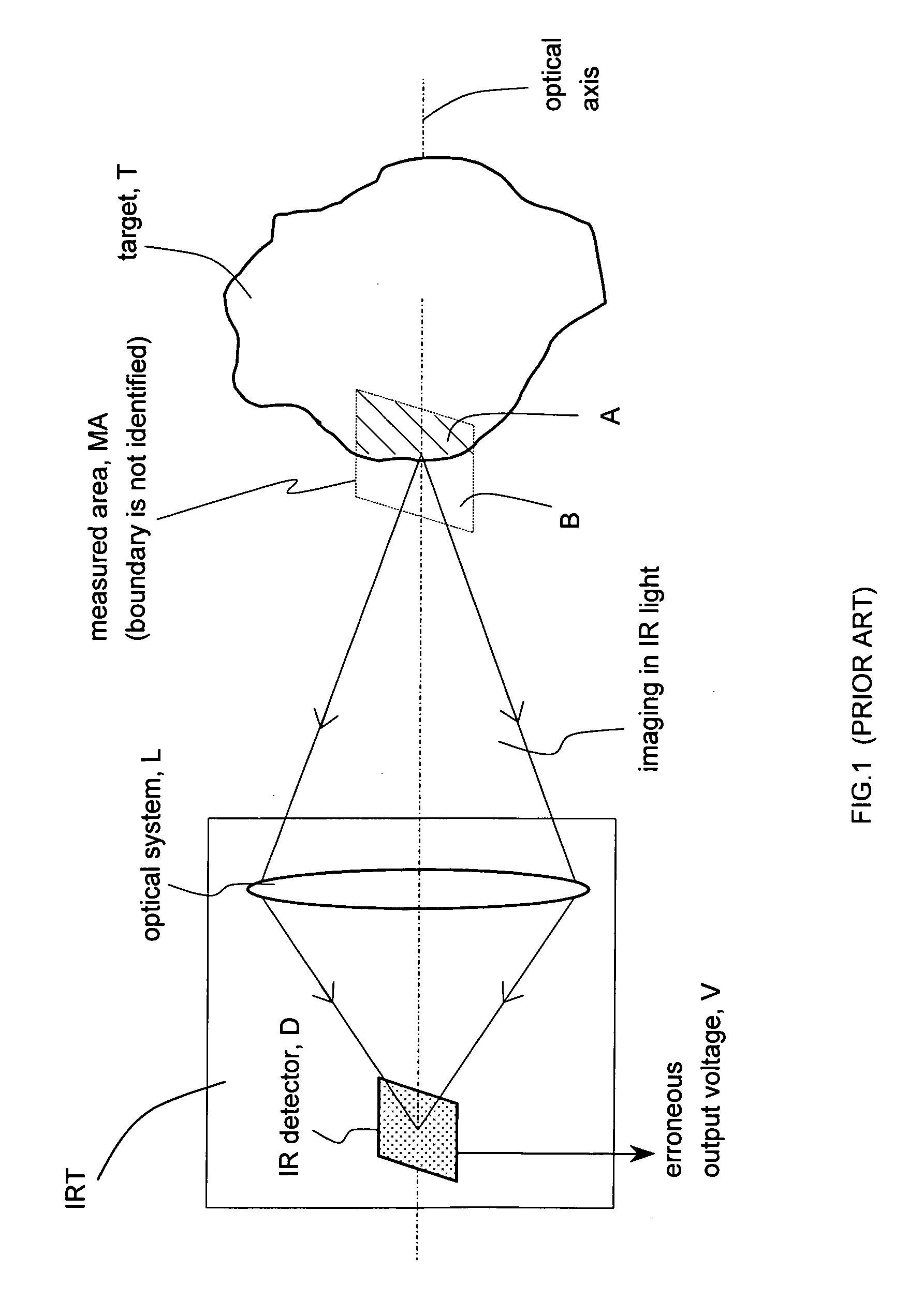
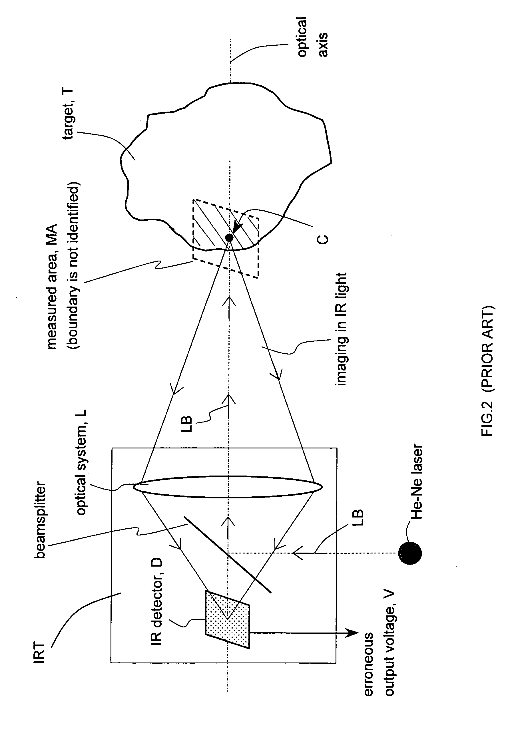
[0022] This invention arose from a long-time need in the field of infrared thermal measurements. Conventional IR thermometers have been unable to precisely and efficiently align the IRT on the target and to identify the target area being measured, so as to allow them not to collect any IR radiation emanating from the background surrounding the target and thus reduce measurement error. This invention provides the first IRT system capable of visible identification of the target area as required for accurate optical alignment between the IRT and the target for error-free measurement. This performance is achieved with a combination of variable-focus achromatic optics and a novel visible light source which is judiciously selected and positioned inside the IRT system so as to form an image that is optically coincident with the image of the IR-detector under any pre-defined imaging conditions. The visible image of the VLS formed on the target surface precisely defines the area of the targe...


PUM


Abstract

A conventional infrared thermometer is equipped with a visible light source having exactly the same size and shape as the infrared detector to illuminate the target so as to visibly identify the area to be thermally measured. The light source is judiciously positioned within the system so as to make the images of the detector and the source formed by achromatic zooming optics coincide on the target surface. As a result, the exact location and dimensions of the target area under test are precisely identified and the system can perform errorless measurements of targets located at variable distances from the thermometer. Alternatively, the system is enabled to errorlessly measure the same target with variable spatial resolution.

Description

RELATED APPLICATIONS [0001] This application is based on U.S. Provisional Application Ser. No. 60 / 581,990, filed Jun. 22, 2004.BACKGROUND OF THE INVENTION [0002] 1. Field of the Invention [0003] This invention is related in general to the field of optical detectors. In particular, it relates to a variable-focus infrared optical detector system used for temperature measurements. [0004] 2. Description of the Related Art [0005] Infrared (IR) detectors are utilized in various applications such as imaging, detection of spectral signatures of chemical species, and remote sensing. In addition, IR detectors are known to be used as IR thermometers (IRTs). The active surface of a typical IR-detector working as a thermometer consists of a series of thermocouple junctions which produce an output voltage in response to IR energy collected and delivered to the detector by the IRT's optical system. Since any target emits IR energy in proportion to its temperature, the output reading of IRTs is dir...

Claims


Application Information

Patent Timeline
Patent Type & Authority Applications(United States)
IPC IPC(8): G01J5/00G01J5/08
CPCG01J5/08G01J5/0806G01J5/0896G01J5/089G01J5/084G01J5/07
Inventor EVEREST, CHARLES E.
Owner EVEREST CHARLES E
Why Eureka
Try Eureka