Phase locked loop with a modulator

a phase lock and modulator technology, applied in the field of phase lock loop with a modulator, can solve the problems of “frequency or phase interference swing”, difficulties, and large bandwidth requirements of modulated data transmission for modern applications in communication technology, and achieve the effects of reducing the step size of the multimodulus divider, reducing the fm interference swing, and reducing the noise of quantization

Active Publication Date: 2005-12-22
TAHOE RES LTD
View PDF4 Cites 20 Cited by
  • Summary
  • Abstract
  • Description
  • Claims
  • Application Information

AI Technical Summary

Benefits of technology

[0021] In accordance with the present invention, the quantization noise is reduced by virtue of the minimum divider step size ΔN being reduced. This step size is less than 1 in accordance with the invention, which means that the phase locked loop can change over with a step size which is smaller than the reference frequency supplied to the phase comparator. The reduction in the minimum divider step size to values of less than 1 is in this case relative to the output frequency of the phase locked loop.
[0022] Reducing the step size of the multimodulus divider results in the instantaneous frequency varying over a smaller frequency range. This in turn reduces the FM interference swing, since the entire quantization noise in the ΣΔ modulator is reduced by the factor of the divider step reduction.

Problems solved by technology

On the other hand, this is opposed by the fact that transmitting modulated data requires a large bandwidth for modern applications in communication technology.
However, this more or less random changeover of the division factor also brings about a change in the frequency over time and therefore produces a “frequency or phase interference swing”.
Difficulties may also arise as a result of the aforementioned demanded adherence to a spectral transmission mask in practically all telecommunication standards.
A fundamental drawback of this solution is its required, highly accurate alignment between the digital filter for compensation and the analog loop filter.
If these alter the bandwidth of the control loop, the digital precompensation causes the higher frequency components to be raised too much or too little.
However, two-point modulation also has the problem of avoiding mismatches between the analog and digital signal paths.

Method used


Image

  • Phase locked loop with a modulator
  • Phase locked loop with a modulator
  • Phase locked loop with a modulator

Examples


Embodiment Construction

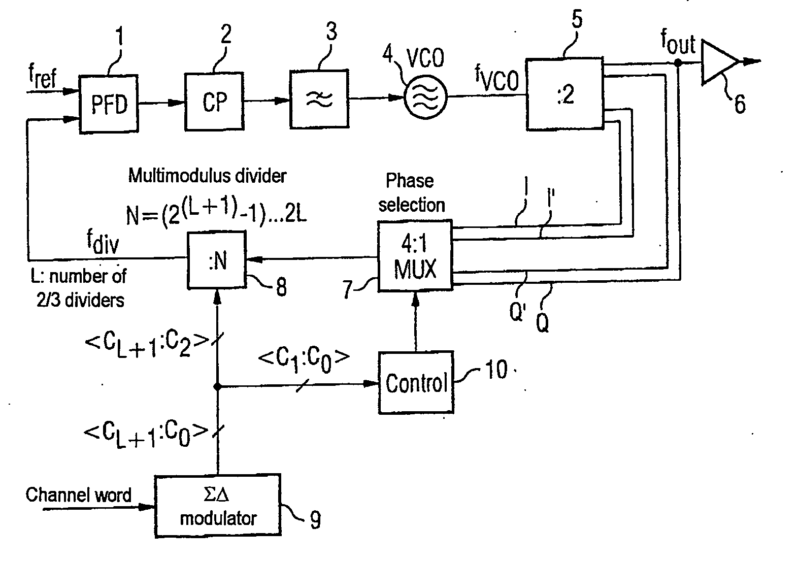
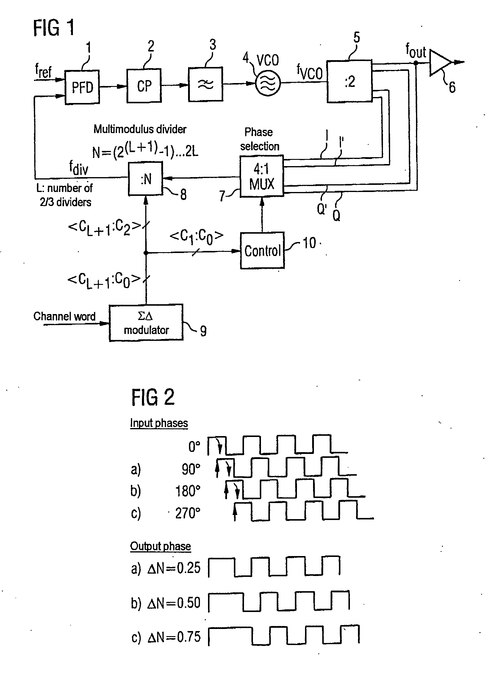
[0041]FIG. 1 shows a phase locked loop with a phase comparator 1 having two inputs and an output. One of the two inputs of the phase detector 1 can have a reference frequency generator connected to it which delivers a reference frequency fref (not shown here). The output of the phase detector 1 has a loop filter 3 connected to it via a charge pump circuit 2, said loop filter being in the form of a low-pass filter. The output of the loop filter 3 has the control input of a voltage-controlled oscillator 4 connected to it. The output of the voltage-controlled oscillator 4, at which a signal at an oscillator frequency fvco is provided, is connected to a frequency divider 5. The frequency divider 5 is, in one example, in the form of a master-slave D-type flip-flop with feedback and has four outputs. The four outputs of the frequency divider 2, which brings about frequency halving, are all designed for tapping off the output frequency fout, which corresponds to half the oscillator frequen...


PUM


Abstract

The invention provides a phase locked loop having a modulator which is based on a ΣΔ fractional N phase locked loop. In the forward path of the PLL, the output of the oscillator has an additional frequency divider which provides the output frequency of the PLL in a plurality of different phases. A multiplexer which is connected upstream of the multimodulus divider in the PLL's feedback path and which is actuated by the ΣΔ modulator, like the divider, selects the respective desired phase. This allows the minimum step size of the division factors to be reduced to values of less than 1 relative to the output frequency, which significantly reduces the quantization noise. The PLL bandwidth may therefore advantageously be the same size as the modulation bandwidth.

Description

REFERENCE TO RELATED APPLICATIONS [0001] This application is a continuation of PCT / DE03 / 03949, filed Dec. 1, 2003 which was not published in English, that claims the benefit of the priority date of German Patent Application No. DE 102 57 181.3, filed on Dec. 6, 2002, the contents of which both are herein incorporated by reference in their entireties.FIELD OF THE INVENTION [0002] The present invention relates to a phase locked loop with a modulator. BACKGROUND OF THE INVENTION [0003] Normally, alterable carrier frequencies for message transmission are generated using phase locked loops (PLLs). [0004] Such a PLL circuit is shown using a block diagram in FIG. 4. In this case, a phase comparator 1 in a forward path actuates an oscillator 4. The actuation is effected via a charge pump circuit 2 and a low-pass filter 3. The phase comparator in a PLL is also called a phase detector or phase / frequency detector. A feedback path in the PLL contains a frequency divider 8 which divides down the...

Claims


Application Information

Patent Timeline
Patent Type & Authority Applications(United States)
IPC IPC(8): H03C3/09H03L7/081H03L7/197
CPCH03C3/0925H03L7/1976H03L7/081H03C3/0933
Inventor PUMA, GIUSEPPE LIWAGNER, ELMAR
Owner TAHOE RES LTD
Why Eureka
Try Eureka