
Data flow graph processing method, reconfigurable circuit and processing apparatus

a data flow graph and processing method technology, applied in the direction of instrumentation, program control, cad circuit design, etc., can solve the problems of large mounting area, higher cost than designing, and circuits for other broadcast modes remain idle all the while, so as to achieve the effect of efficient processing and configuration of operation

Active Publication Date: 2005-12-22
GK BRIDGE 1
View PDF19 Cites 30 Cited by
  • Summary
  • Abstract
  • Description
  • Claims
  • Application Information

AI Technical Summary

Benefits of technology

[0011] The present invention has been done in view of the aforementioned situation and its object is to provide a technique capable of efficiently processing a data flow graph necessary to configure the operation of a reconfigurable circuit.

Problems solved by technology

Designing an LSI by using an FPGA, however, results in a larger mounting area and a higher cost than designing it with an application specific IC (ASIC).
Therefore, the circuits for the other broadcast modes remain idle all the while.
Also, since a complex wiring pattern is developed for connection between basic cells, the wiring tends to be long.
Moreover, the structure in which a large number of switches are connected to a single wire gives rise to a long delay.
For these reasons, FPGA-based LSIs are generally used for testing and experimenting purposes only and are not suited to mass production, considering the mounting efficiency, performance and cost.
Another problem is that, since configuration information needs to be transmitted to a large number of basic cells of LUT-based logic implementation, it takes a considerable period of time to configure the circuit.
For this reason, an FPGA is not suitable for usage in which instantaneous switching between circuit configurations is needed.

Method used


Image

  • Data flow graph processing method, reconfigurable circuit and processing apparatus
  • Data flow graph processing method, reconfigurable circuit and processing apparatus
  • Data flow graph processing method, reconfigurable circuit and processing apparatus

Examples


Embodiment Construction

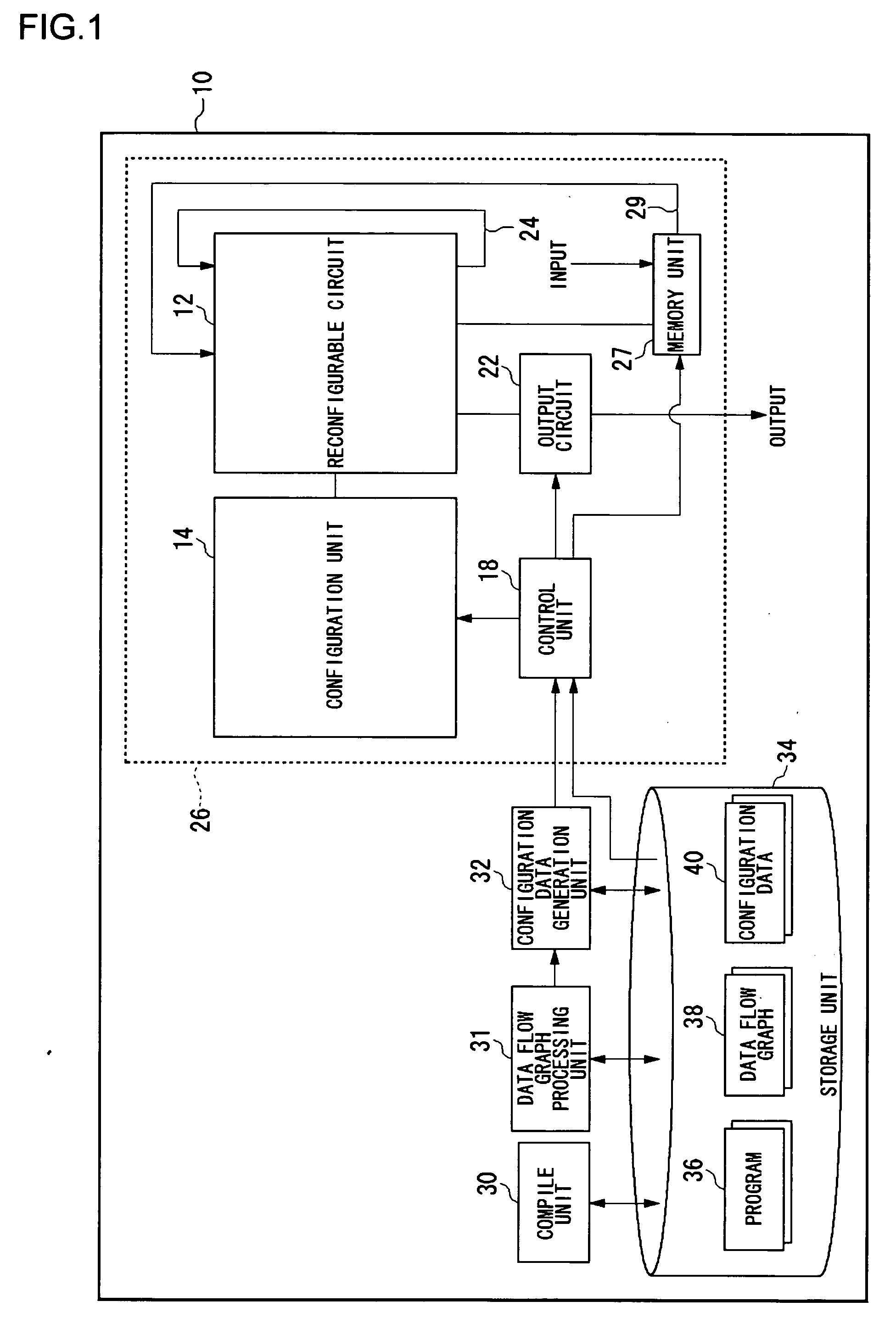
[0031]FIG. 1 illustrates the structure of a processing apparatus 10 according to an example of the present invention. The processing apparatus 10 is provided with an integrated circuit apparatus 26. The circuit configuration of the integrated circuit apparatus 26 is reconfigurable. The integrated circuit apparatus 26 is formed as a single chip and is provided with a reconfigurable circuit 12, a configuration unit 14, a control unit 18, an output circuit 22, a memory unit 27 and route units 24 and 29. The function of the reconfigurable circuit 12 is changeable by changing the configuration thereof.

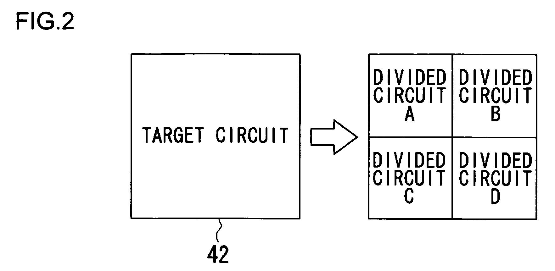
[0032] The configuration unit 14 supplies configuration data 40 to the reconfigurable circuit 12 to form a target circuit. The configuration unit 14 may be formed as a command memory that outputs stored data by referring to the count of a program counter. In this case, the control unit 18 controls the output of the program counter. In this sense, the configuration data 40 maybe referred to...


PUM


Abstract

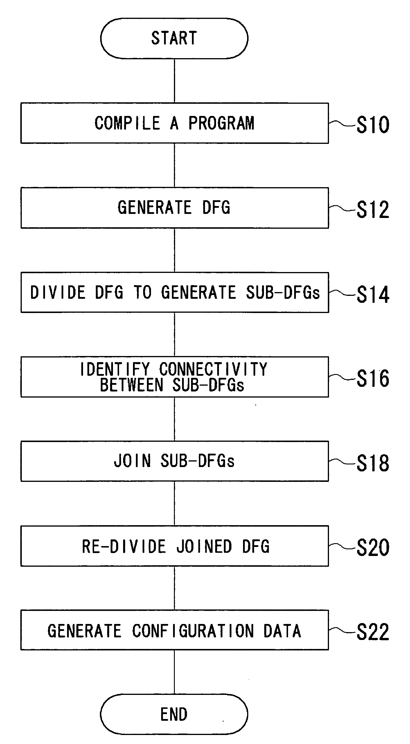
A data flow graph processing method divides at least one DFG generated into a plurality of sub-DFGs, in accordance with the number of logic circuits in a circuit set in a reconfigurable circuit. When the reconfigurable circuit is provided with a structure including multiple-row connections, the number of columns in the sub-DFG is configured to be equal to or fewer than the number of logic circuits per row in the reconfigurable circuit. Subsequently, the sub-DFGs are joined so as to generate a joined DFG. The number of columns in the joined DFG is also configured to be equal to or fewer than the number of columns per row in the reconfigurable circuit. The joined DFG is redivided to sizes with number of rows equal to or fewer than the number of rows in the reconfigurable circuit, so as to generate subjoined DFGs mappable into the reconfigurable circuit.

Description

BACKGROUND OF THE INVENTION [0001] 1. Field of the Invention [0002] The present invention relates to a technique for processing a data flow graph necessary for configurable the operation of a reconfigurable circuit with variable functions. [0003] 2. Description of the Related Art [0004] Recently, efforts have been made toward the development of a reconfigurable processor in which the hardware operation is changeable in accordance with a target application. In building architecture that implements a reconfigurable processor, a digital signal processor (DSP) or a field programmable gate array (FPGA) is used. [0005] A field programmable gate array (FPGA) allows relatively flexible circuit configuration by permitting circuit data to be written after an LSI is fabricated. FPGAs are used to design dedicated hardware. An FPGA includes basic cells each comprised of a look-up table (LUT) for storing a truth table of a logic circuit and an output flip-flop and of programmable wiring resources...

Claims


Application Information

Patent Timeline
Patent Type & Authority Applications(United States)
IPC IPC(8): G06F9/45G06F17/50
CPCG06F17/5045G06F15/7867G06F30/30
Inventor OZONE, MAKOTO
Owner GK BRIDGE 1
Learn More