Tornado torch igniter

a technology of torch igniter and torch, which is applied in the direction of electric ignition installation, machines/engines, mechanical equipment, etc., can solve the problems of affecting the combustion chamber, so as to reduce the exposure to hot combustion gases, and reduce the effect of retractable igniter

Active Publication Date: 2005-12-29
H2 IP UK LTD
View PDF12 Cites 25 Cited by
  • Summary
  • Abstract
  • Description
  • Claims
  • Application Information

AI Technical Summary

Benefits of technology

[0006] In operation, compressed air enters through at least one air inlet hole and into the generally annular passage before passing into the plurality of channels and into the mixing chamber. Compressed air also passes through a plurality of air swirl holes in the outer housing to create a tornado effect along the wall of the mixing chamber for effectively cooling the mixing chamber walls as well as for providing excellent flame stability. A flame is created when fuel from the at least one fuel passage is

Problems solved by technology

Because of this reliability issue, a compromise of configurations evolved resulting in a retractable igniter.
One disadvantage to a torch igniter with liquid fuel is the blockage of the fuel injector that can be due to debris or coking of the fuel due to its operating temperature.
Should the fuel flow to the torch

Method used


Image

  • Tornado torch igniter
  • Tornado torch igniter
  • Tornado torch igniter

Examples


Embodiment Construction

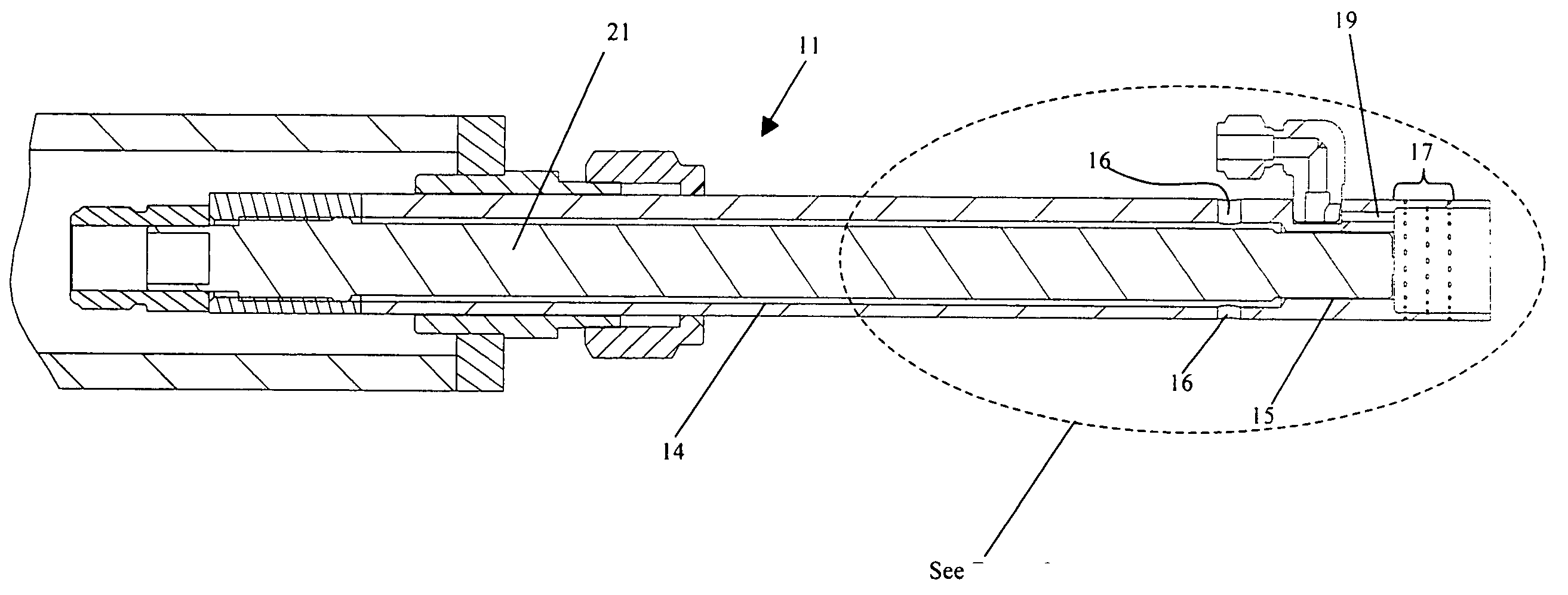
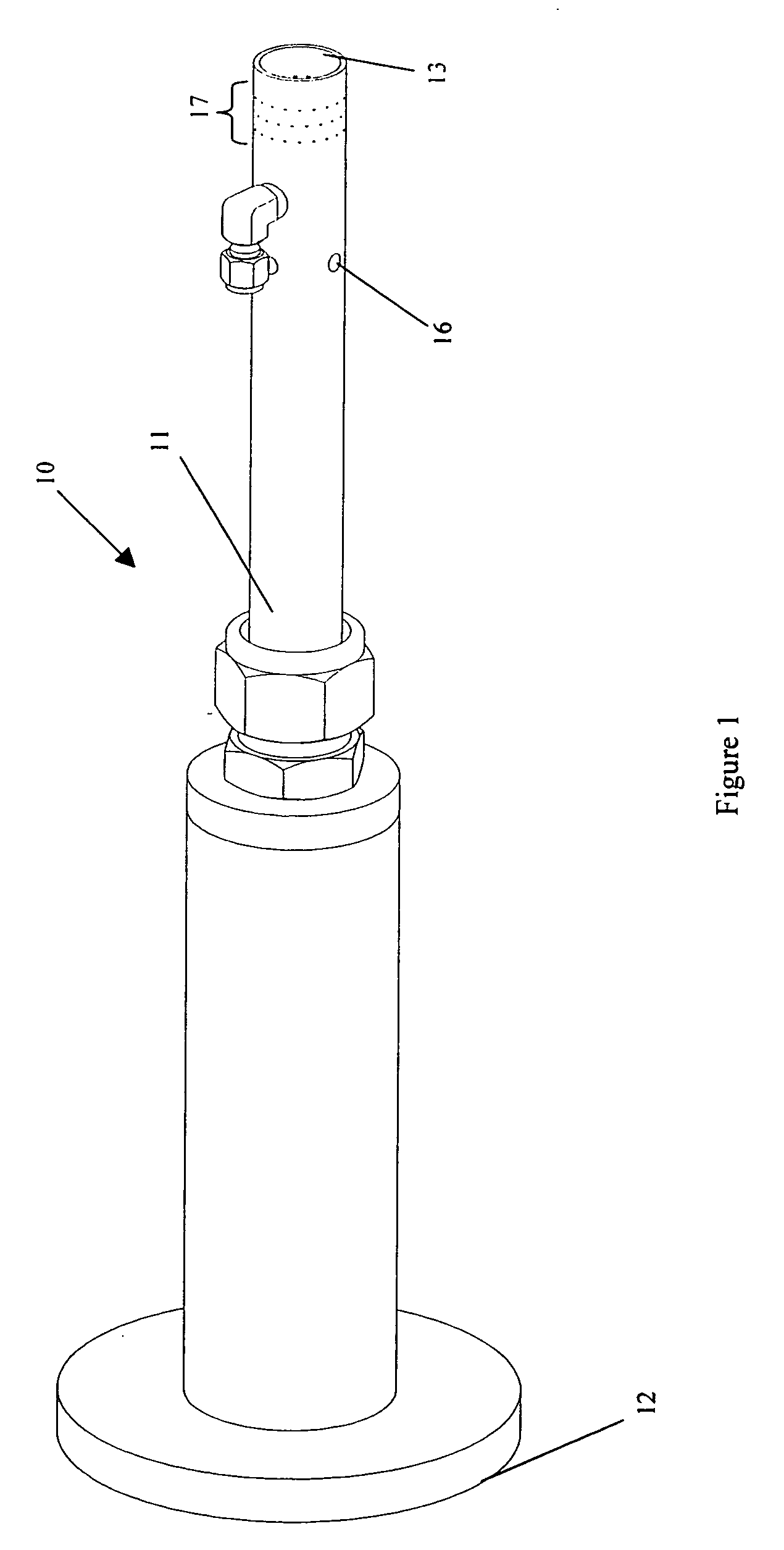
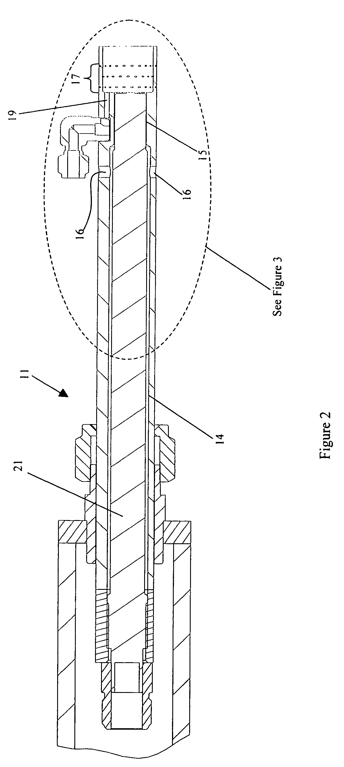
[0016] Referring to FIGS. 1-3, an ignition system 10 for a gas turbine combustor is shown in detail and preferably comprises an outer housing 11, which further comprises a first end 12, second end 13, a first inner wall 14, and a second inner wall 15 located proximate second end 13. Other features of outer housing 11 include at least one air supply hole 16 that extends through first inner wall 14 and a plurality of air swirl holes 17 that are located proximate second end 13. Air swirl holes 17 are preferably located in at least one row in outer housing 11 as shown in FIGS. 3, 5, and 6. Referring now to FIGS. 4 and 6, and located proximate second end 13, and along second inner wall 15 is at least one raised surface 18. Also located in outer housing 11, as can best be seen in FIG. 3, is at least one fuel passage 19 that extends towards second end 13 for injecting a fuel such as natural gas. Located adjacent second end 13 of outer housing 11 is a mixing chamber 20. In order to provide ...


PUM


Abstract

An ignition system having improved reliability for a gas turbine combustor is disclosed. The ignition system comprises an outer housing having at least one fuel passage and an electrode extending therethrough forming a generally annular passage for cooling air to pass to a mixing chamber. Fuel and air mix in the mixing chamber to form a combustible mixture that is ignited by the electrode. The outer housing further comprises a plurality of air swirl holes to effectively cool the walls of the mixing chamber as well as to provide improved flame stability.

Description

TECHNICAL FIELD [0001] The present invention generally relates to gas turbine engines and more specifically to an ignition system that provides an improved starting reliability for a combustion system of the gas turbine engine. BACKGROUND OF THE INVENTION [0002] Combustion within gas turbine engines is typically initiated by an ignition system having a heating source. Historically, two different types of igniters have been used, one located within the combustion chamber and the other located outside of the combustion chamber. It is preferred from a durability point of view to have the ignition system located outside of the combustion chamber such that it is not directly in contact with the hot combustion gases that can reduce component life. However, this arrangement requires the ignition system to be extremely reliable given its proximity to the combustible mixture. Because of this reliability issue, a compromise of configurations evolved resulting in a retractable igniter. Once ig...

Claims


Application Information

Patent Timeline
IPC IPC(8): F02B19/00F02C7/266F02M57/06F02P23/00
CPCF02C7/266F05D2210/10F05D2210/11F05D2210/12
Inventor STUTTAFORD, PETERHENRIQUEZ, JOHNECONOMO, PAUL
Owner H2 IP UK LTD
Why Eureka
Try Eureka