Method and apparatus for noise compensation in an oscillator circuit

a technology of oscillator circuit and noise compensation, which is applied in the direction of oscillator generator, pulse automatic control, electrical apparatus, etc., can solve the problems of unsatisfactory jitter or noise associated with the output of the vco

Active Publication Date: 2005-12-29
SKYWORKS SOLUTIONS INC
View PDF5 Cites 7 Cited by
  • Summary
  • Abstract
  • Description
  • Claims
  • Application Information

AI Technical Summary

Problems solved by technology

The nonlinear capacitance can cause the instantaneous output frequency of the VCO to vary as a function of VCO amplitude, which can result in undesirable jitter or noise associated with the output of the VCO.

Method used


Image

  • Method and apparatus for noise compensation in an oscillator circuit
  • Method and apparatus for noise compensation in an oscillator circuit
  • Method and apparatus for noise compensation in an oscillator circuit

Examples


Embodiment Construction

)

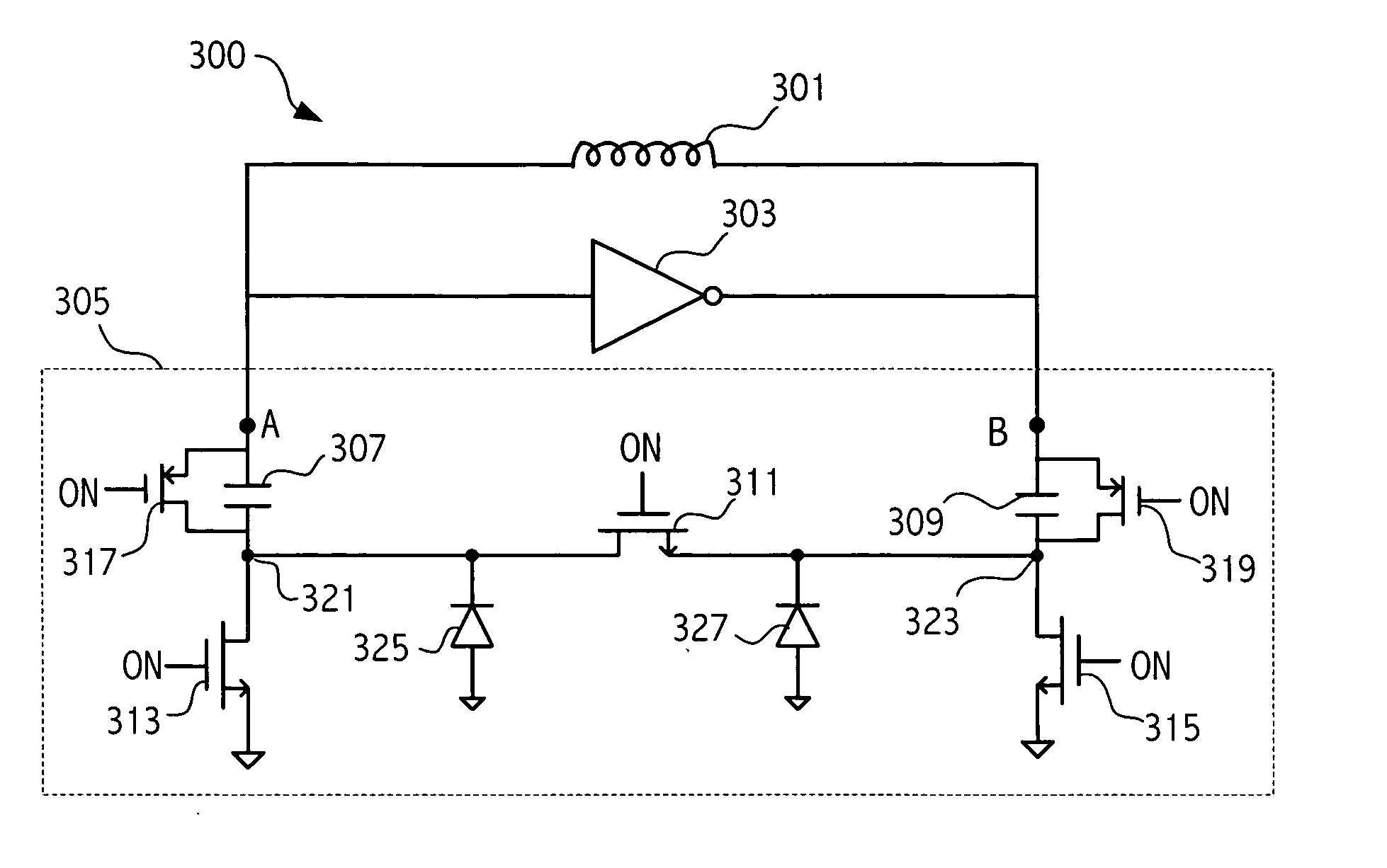
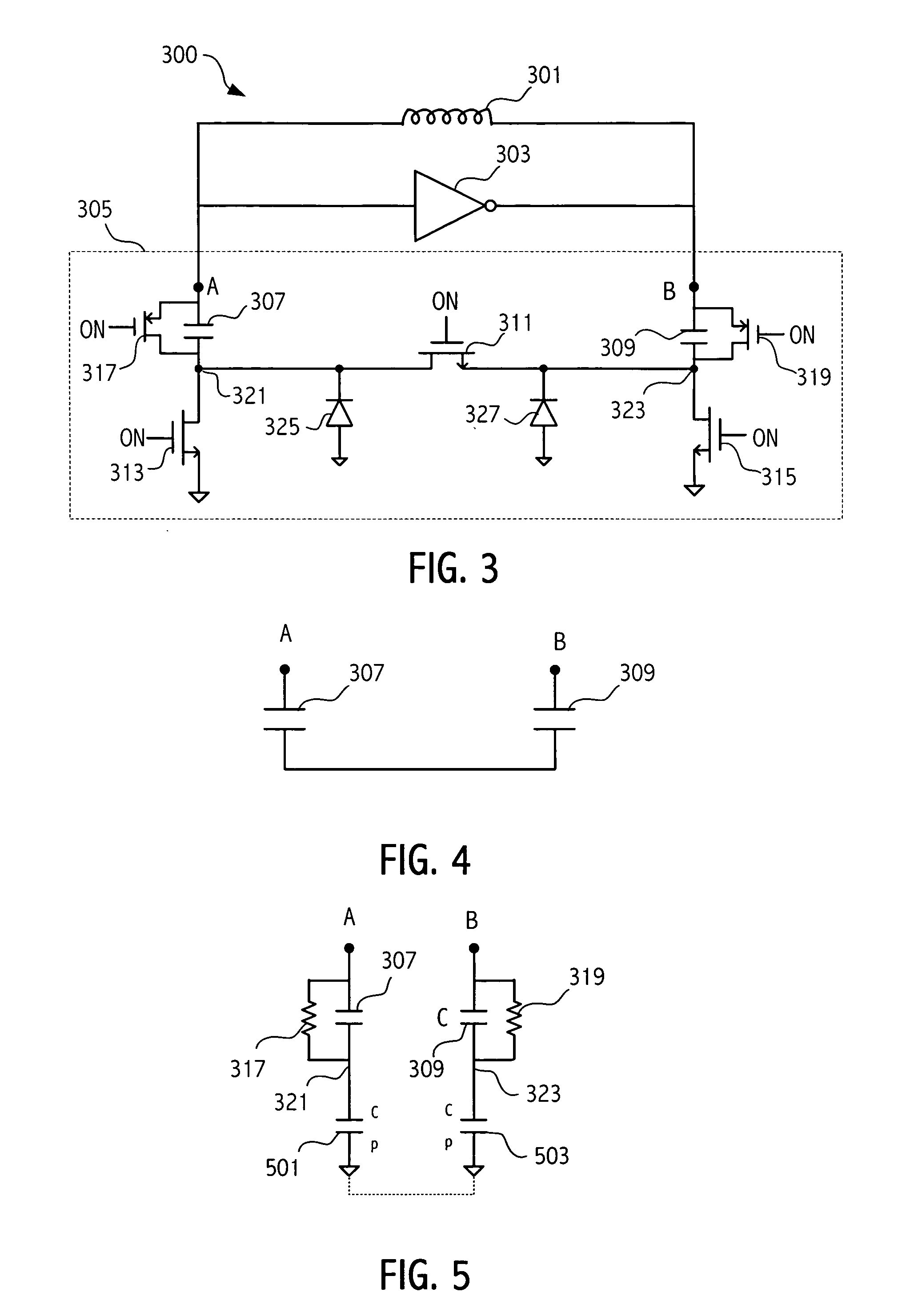
[0019] Referring to FIG. 3 a portion of a VCO 300 is illustrated that includes an inductor 301, a gain circuit 303 and a portion 305 of a variable capacitance circuit. The portion 305 of the variable capacitance circuit includes a capacitor 307 and a capacitor 309 that are selectably coupled by a low resistance switch 311. In one embodiment, the switch 311 is implemented as an N-channel MOS transistor. When the switch 311 is turned on by a control voltage ON, the capacitors appear as serially coupled capacitors between tank circuits node A and B as illustrated in FIG. 4. In addition, transistors 313 and 315 are turned on when switch 311 is turned on. Transistors 313 and 315 are small transistors weakly coupling the capacitor to ground through a relatively high resistance path.

[0020] When the switch is OFF (ON=0), p-channel transistors 317 and 319 are turned on to provide, respectively, a relatively high resistance path between node A and node 321 and node B and node 323. That ensu...


PUM


Abstract

A variable capacitance circuit includes a first and a second capacitor. A switch having an associated first nonlinear capacitance, selectively couples the first and second capacitors. To compensate for the first nonlinear capacitance, a second nonlinear capacitance is coupled to the switch that has a capacitance value responsive to a change in voltage that moves in a direction of change opposite to a direction of change of the first nonlinear capacitance.

Description

BACKGROUND [0001] 1. Field of the Invention [0002] This application relates to oscillator circuits and more particularly to suppression of noise in oscillator circuits. [0003] 2. Description of the Related Art [0004] A voltage controlled oscillator (VCO) may be implemented using LC tank circuits. The oscillating frequency of the VCO is proportional to √{square root over (1 / LC)}. Thus, it is common to use variable capacitance circuits to vary the capacitance (C) and thus the output frequency of the VCO. Voltage controlled oscillators are commonly found in such applications as phase-locked loop circuits. FIG. 1 illustrates a high level block diagram of a phase-locked loop 100. In the phase-locked loop 100 an input signal 101 and a feedback signal 103 are coupled to a phase / frequency detector 105 that determines the phase / frequency difference between the input signal 101 and the feedback signal 103. That difference is supplied to a loop filter 104, which supplies a control voltage on n...

Claims


Application Information

Patent Timeline
Patent Type & Authority Applications(United States)
IPC IPC(8): H03B5/04H03L7/00H03L7/099
CPCH03B5/04H03L7/099
Inventor ZHANG, LIGANGHUANG, YUNTENG
Owner SKYWORKS SOLUTIONS INC
Why Eureka
Try Eureka