Power conversion system and method

Inactive Publication Date: 2005-12-29
GENERAL ELECTRIC CO
View PDF6 Cites 13 Cited by
  • Summary
  • Abstract
  • Description
  • Claims
  • Application Information

AI Technical Summary

Benefits of technology

[0007] In accordance with one aspect of the present technique, a power conversion system may comprise a converter coupled to a power source and configured to convert a fixed frequency, fixed voltage AC power to AC power with a variable frequency, voltage or current. The power conversion system may further comprise a process control unit coupled to the converter and configured to control the output power by adjusting voltage, current or frequency of the output signal. The power conversion system may further comprise an input power quality control unit coupled to the converter and configured to control the input power

Problems solved by technology

However, conventional power conversion systems may suffer from poor power quality typically associated with the inability to adjust the input power factor and harmonic content of the input currents.
Due to operation at the typically low

Method used


Image

  • Power conversion system and method
  • Power conversion system and method
  • Power conversion system and method

Examples


Example

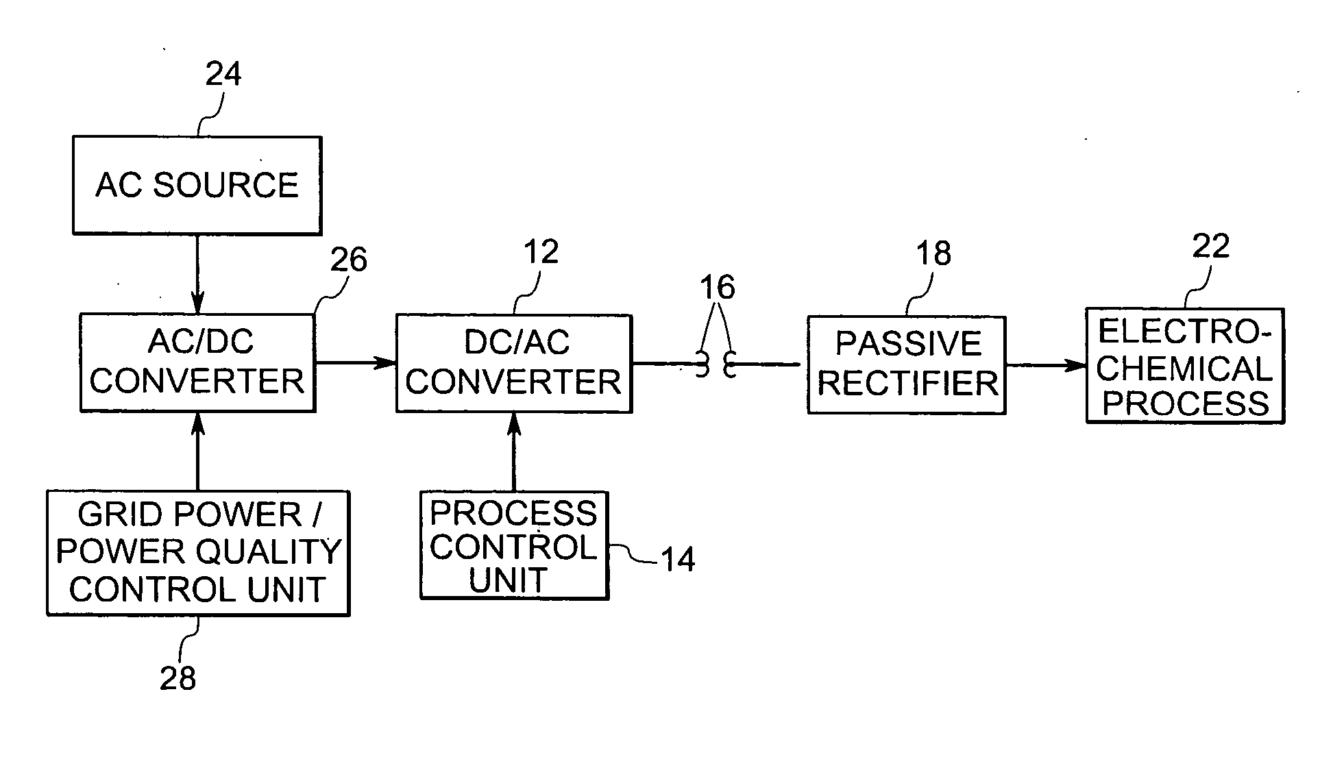
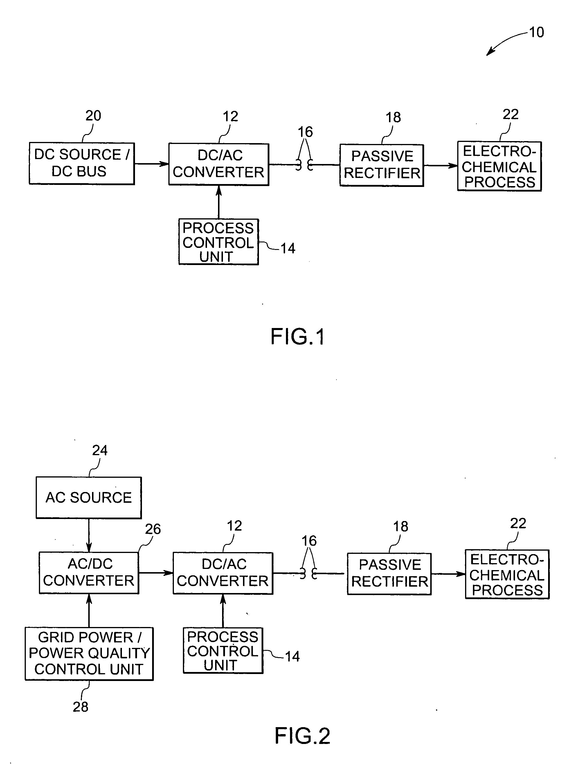
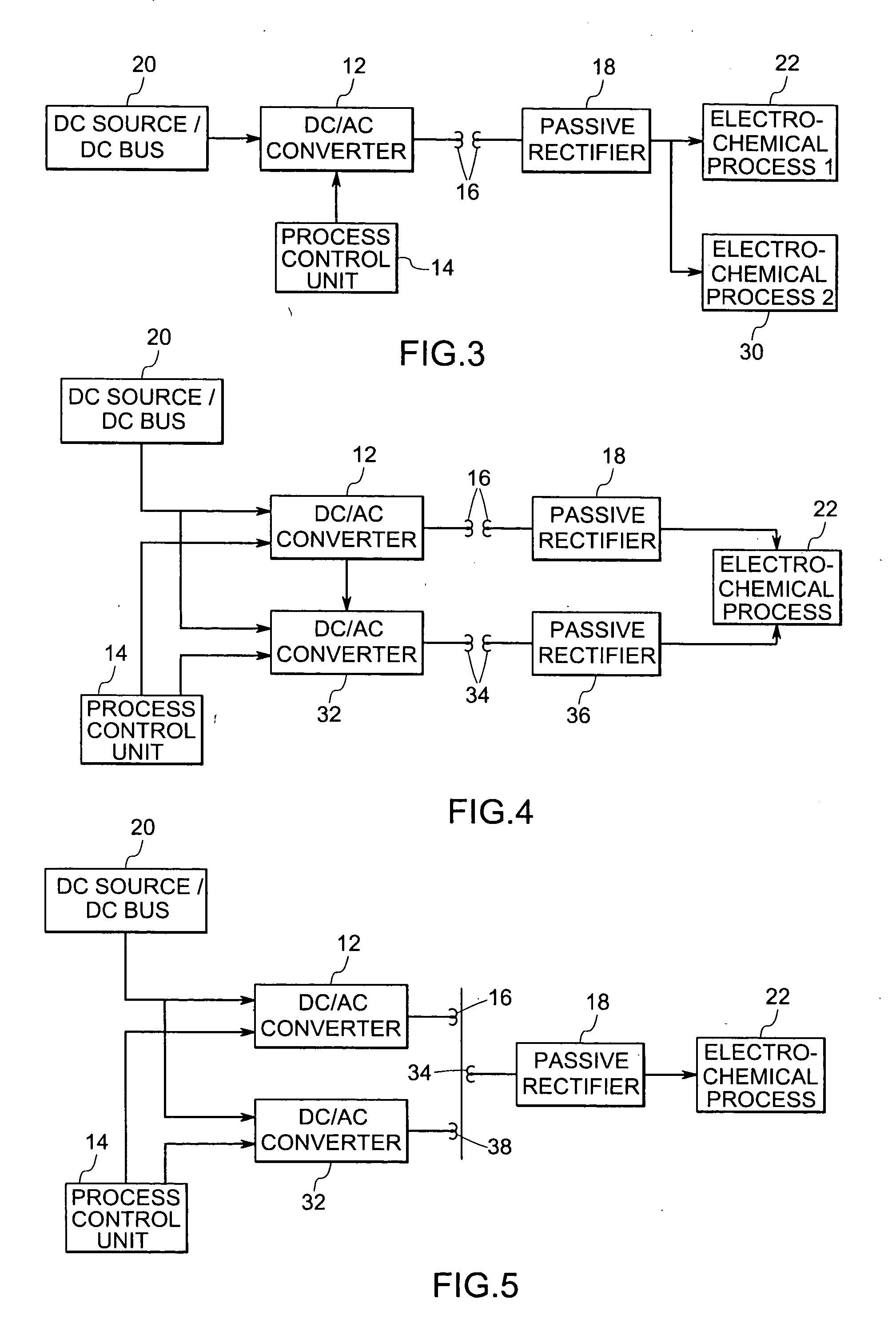
[0016] Referring now to FIG. 1, a power conversion system, represented generally by the reference numeral 10, is illustrated. The power conversion system 10 comprises a converter 12, a process control unit 14, a transformer 16, and a passive rectifier 18. In the illustrated embodiment, the converter 12 may be coupled to a DC power source 20. The DC power source 20 may include a photovoltaic system, a solar cell, a battery, a DC transmission line, a high voltage DC bus or the like.

[0017] The converter 12 is configured to convert a power signal transmitted from the DC power source 20 to a controllable AC power signal. As appreciated by those skilled in the art, the converter 12 may include a single-phase inverter, a multi-phase inverter, or a multi-level inverter, or a parallel configuration or a combination thereof. The process control unit 14 is coupled to the converter 12 and is configured to control various characteristics such as frequency, magnitude, power factor, ripple conten...


PUM

PropertyMeasurementUnit
Poweraaaaaaaaaa

Abstract

A power conversion system comprises a converter coupled to a power source and configured to convert a DC power to a variable AC power signal. The power conversion system may further comprise a process control unit coupled to the converter and configured to control the variable AC power signal. The power conversion system may also further comprise a transformer having a primary side and a secondary side, the primary side receiving the variable AC power signal from the converter and a passive rectifier coupled to the secondary side of the transformer. The transformer may be adapted to provide galvanic isolation between the power source and an electro-chemical process. The passive rectifier is adapted to convert the variable AC power to the variable DC power and to deliver the variable DC power to the electro-chemical processing unit.

Description

BACKGROUND [0001] The invention relates generally to power conversion systems, and more specifically to a power conversion system and method that may be adapted for use in connection with an electro-chemical process. [0002] Electro-chemical processes include processes where metal is deposited on a substrate by passing a current through an electrolyte. A typical electro-chemical cell such as an electrolyzer may include an anode, which is the source of the material to be deposited. An electrolyte, which is a medium through which metal ions are exchanged, may also be included. An electrolyzer may further include a cathode, which may comprise the substrate to be coated. The anode may be connected to the positive terminal of a power supply and the cathode may be connected to the negative terminal of the power supply. When a voltage is applied between the anode and the cathode, positive metal ions from the electrolyte are attracted to the cathode and deposited thereon. As replenishment fo...

Claims


Application Information

Patent Timeline
IPC IPC(8): B23H3/02H02M3/335
CPCH02M3/33523B23H3/02
Inventor TEICHMANN, RALPH
Owner GENERAL ELECTRIC CO
Why Eureka
Try Eureka