
Link adaptation

a technology of link adaptation and adapter, applied in the field of link adaptation, can solve the problems of no signaling mechanism specified which would allow a receiver, and does not provide any protocol means for a receiver, and achieve the effects of reducing data rate, excellent performance, and fast changing

Inactive Publication Date: 2005-12-29
IBM CORP
View PDF9 Cites 38 Cited by
  • Summary
  • Abstract
  • Description
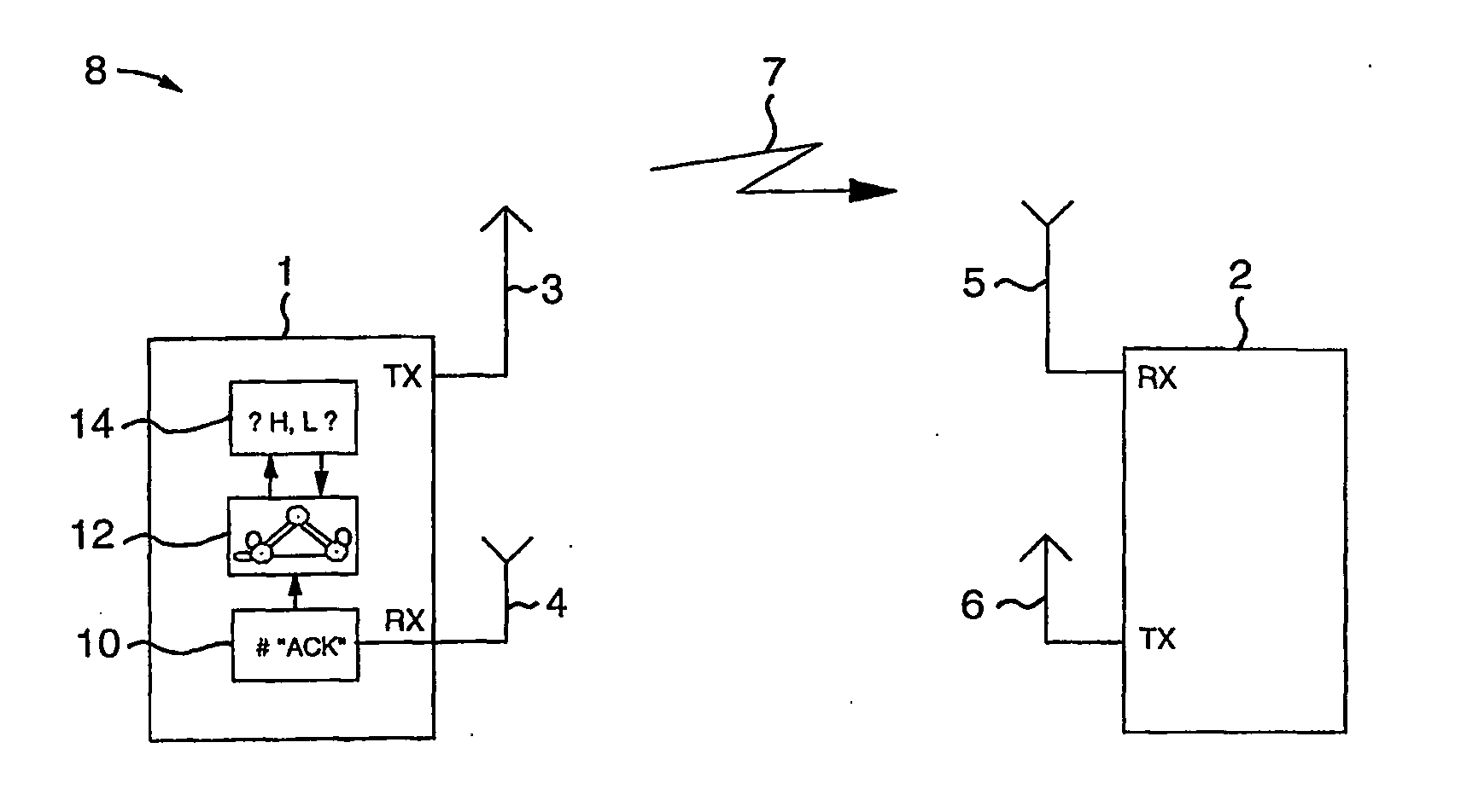
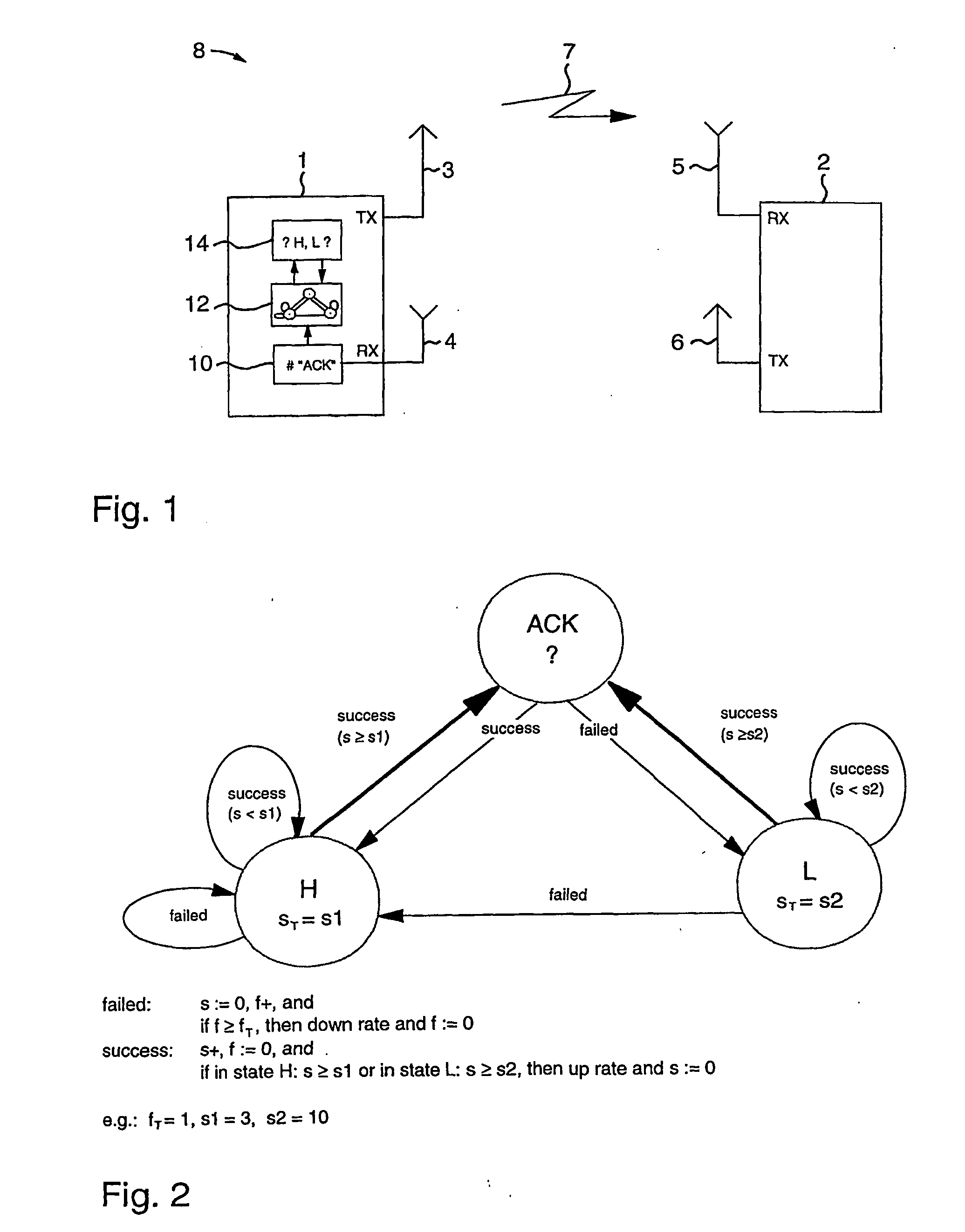
  • Claims
  • Application Information

AI Technical Summary

Benefits of technology

[0009] In accordance with the present invention, a method for adapting a transmission parameter in a transmitting node of a data communication system to the current link quality of a data communication channel is provided. The adapted transmission parameter is selected by the transmitting node from a set of transmission parameters in dependence on a number of successful transmissions s. The number of successful transmissions s is compared in the transmitting node against one of a first value s1 corresponding to a first state of the transmitting node and a second value s2 corresponding to a second state of the transmitting node. The method comprises in the transmitting node the steps of (a) counting the number of successful transmissions s; (b) selecting the adapted transmission parameter (b1) in response to the number of successful transmissions s equaling or exceeding the first value s1 when the transmitting node is in the first state, and (b2) in response to the number of successful transmissions s equaling or exceeding the second value s2 when the transmitting node is in the second state; and in dependence of the result of a following transmission, operating the transmitting node in one of the first state and the second state. The first value s1 is hereafter also referred to as first threshold value s1 and the second value s2 is hereafter also referred to as second threshold value s2.
[0010] Preferably, the second threshold value s2 is larger than the first threshold value s1, because then the first state can correspond to a link with fast changing quality and the second state can correspond to a link with slow changing quality.
[0011] In an embodiment the method can be used for adapting a variable data rate to the link quality, thereby supporting multiple transmission rates. Selecting the adapted transmission parameter in step (b) which is also contemplated as switching to the adapted transmission parameter then comprises switching to a different data rate. This allows the adaptation of the variable data rate to present channel conditions. In a further embodiment, the step of selecting the adapted transmission parameter can further comprise selecting a higher data rate from several data rates. Also a packet length different to the length employed before can be used. Moreover, the variable data rate, the different packet lengths, or other parameters can be combined. This shows the advantage that several transmission parameters can be adapted to the respective channel conditions.
[0012] The step of operating the transmitting node in the second state further comprises the transition to the first state in the event of a faulty transmission. This has the advantage that it can be switched directly from the second state to the first state, thereby coping with fast changing channel conditions.
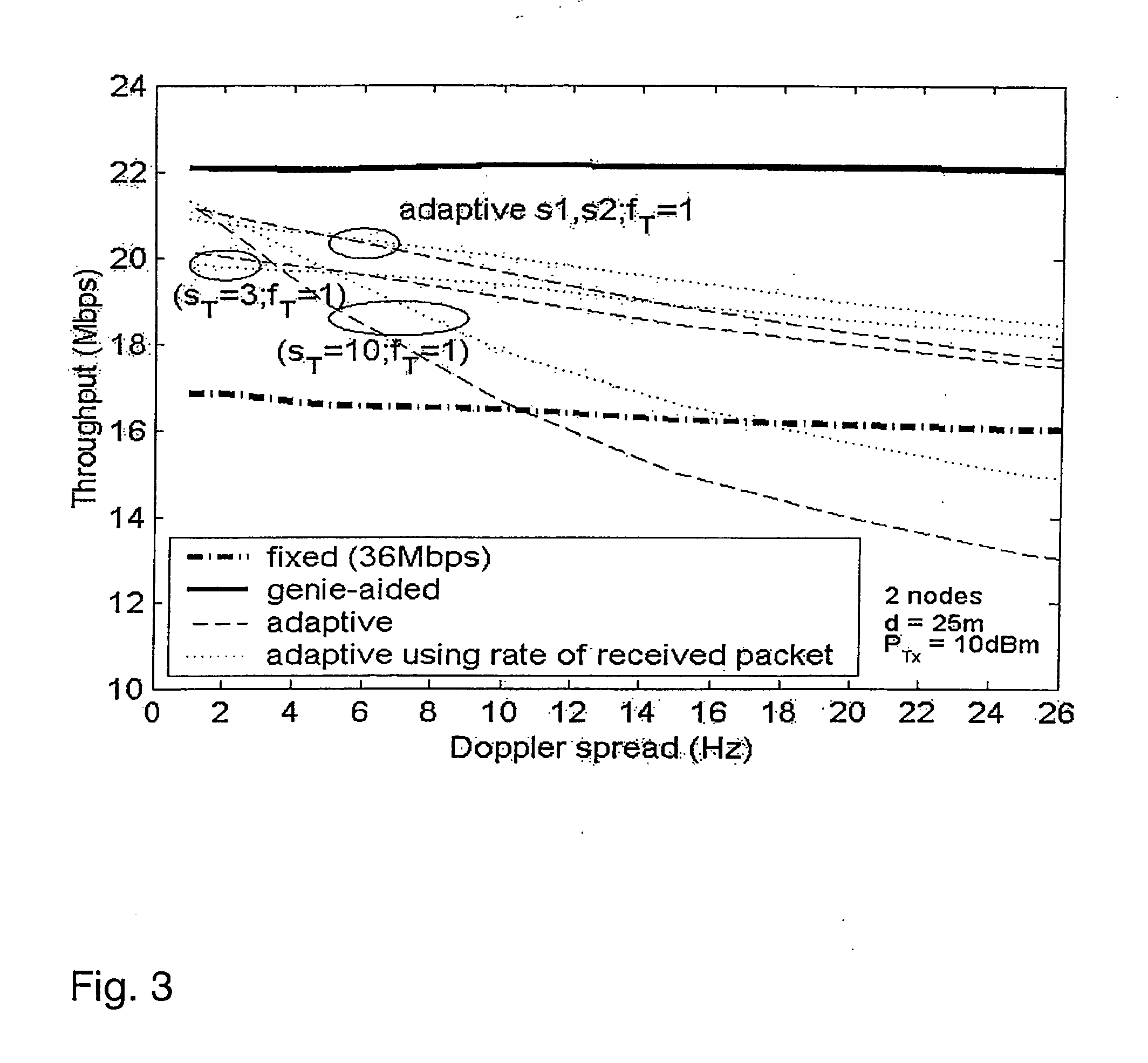
[0013] Setting the first threshold value s1 to 3 and the second threshold value s2 to 10 leads to an excellent performance in time-varying channels.
[0014] The method can further comprise counting a number of faulty transmissions f and selecting the adapted transmission parameter at a threshold of the number of faulty transmissions fT. This has the advantage that also faulty transmissions are considered and a suitable reaction, e.g. reducing the data rate, can be applied accordingly. In other words, it can, for example, mean switching to a lower data rate immediately after one faulty transmission.

Problems solved by technology

The main issues for an efficient link adaptation mechanism are the determination of the parameters to be used for the link quality estimation, e.g. packet error rate, signal to noise ratio, received signal strength, carrier to interference ratio, etc., how to measure them, and how to select the appropriate rate out of the measurement results.
Furthermore, there is no signaling mechanism specified which would allow a receiver to inform the transmitter about the quality of the communication channel or the rate to be used.
It even does not provide any protocol means for a receiver to inform the transmitter about the actual link quality or the transmission rate to be used.

Method used


Image

  • Link adaptation
  • Link adaptation
  • Link adaptation

Examples


Embodiment Construction

[0029] Although the present invention is applicable in a broad variety of transmission applications it will be described with the focus put on an application to wireless systems, i.e. Wireless Local Area Networks (WLAN), using orthogonal frequency division multiplexing (OFDM) as employed in the WLAN standards IEEE 802.11a and HIPERLAN / 2. Before embodiments of the present invention are described, some basics, in accordance with the present invention, are addressed.

[0030] As the invention takes advantage of the so-called error recovery procedure defined in the MAC (medium access control) layer of the IEEE 802.11 standard, this error recovery procedure is described in more detail below.

[0031] The IEEE 802.11 basic access procedure is a distributed procedure based on the known Carrier Sense Multiple Access (CSMA) method used in Ethernet LANs (local area networks). A station with a pending data packet has to sense the state of the wireless medium before it can transmit. If the medium i...


PUM


Abstract

The present invention discloses an apparatus and method for adapting a transmission parameter in a transmitting node of a data communication system to the current link quality of a data communication channel. The adapted transmission parameter is selected by the transmitting node from a set of transmission parameters in dependence on a number of successful transmissions. The number of successful transmissions is compared in the transmitting node against one of a first threshold value corresponding to a first state of the transmitting node and a second threshold value corresponding to a second state of the transmitting node. The method comprises in the transmitting node the steps of (a) counting the number of successful transmissions; (b) selecting the adapted transmission parameter (b1) in response to the number of successful transmissions equaling or exceeding the first threshold value when the transmitting node is in the first state, and (b2) in response to the number of successful transmissions equaling or exceeding the second threshold value when the transmitting node is in the second state; and in dependence of the result of a following transmission, operating the transmitting node in one of the first state and the second state.

Description

TECHNICAL FIELD [0001] The present invention is related to an apparatus and method for adapting transmission parameters to the current quality of a transmission channel. More particularly, the invention allows to adapt a variable data rate or a packet length or both to the channel conditions in a wireless local area network. BACKGROUND OF THE INVENTION [0002] Wireless local area networks (WLANs) have been designed for data communication and have found widespread acceptance and proliferation in the industry. Two wireless broadband LANs (WLANs) are standardized in the 5 GHz band, namely IEEE 802.11a and ETSI HIPERLAN / 2. The physical layers of both standards are very similar: they both use a modulation technique called “Orthogonal Frequency Division Multiplexing (OFDM)” and can provide up to 8 different transmission modes with data rates ranging from 6 Mbps up to 54 Mbps. This multi-rate capability enables a WLAN station to select a transmission mode which is best appropriate to the cu...

Claims


Application Information

Patent Timeline
Patent Type & Authority Applications(United States)
IPC IPC(8): H04L1/16H04L1/00H04L29/06H04L29/08
CPCH04L1/0002Y02B60/31H04L1/0026H04L1/0007Y02D30/50H04L1/00
Inventor TRUONG, HONG LINHBARRETO, ANDRE NOLLJELITTO, JENA
Owner IBM CORP
Learn More