Method and apparatus for coding images with different image qualities for each region thereof, and method and apparatus capable of decoding the images by adjusting the image quality

a technology of image quality and region, applied in the field of image coding methods, image coding apparatuses, image pickup apparatuses, etc., can solve the problems of troublesome selection of roi regions, undesired moving bodies, and inability to select roi regions during the shooting of moving pictures, so as to reduce the code amount and reduce the image quality of non-regions of interest. , the effect of reducing the code amoun

Inactive Publication Date: 2005-12-29
SANYO ELECTRIC CO LTD
View PDF10 Cites 33 Cited by
  • Summary
  • Abstract
  • Description
  • Claims
  • Application Information

AI Technical Summary

Benefits of technology

[0010] According to this mode of carrying out the present invention, the image quality of a non-region-of-interest can be lowered while the image quality of a region of interest is kept at the user-intended level, so that the code amount can be reduced. The image quality of a region of interest can also be lowered on purpose.
[0012] According to this mode of carrying out the present invention, the image quality of a non-region-of-interest can be lowered while the image quality of a region of interest is kept at the user-intended level, so that the code amount can be reduced. The image quality of a region of interest can also be lowered on purpose. The object can be automatically tracked even without the recognition of a region of interest per frame and any setting by a user operation.
[0016] According to this mode of carrying out the present invention, the image quality of a non-region-of-interest can be lowered while the image quality of a region of interest is kept at the user-intended level, so that the code amount can be reduced. The image quality of a region of interest can also be purposely lowered.
[0018] According to this mode of carrying out the present invention, the image quality of a non-region-of-interest can be lowered while the image quality of a region of interest is kept at the user-intended level, so that the code amount can be reduced. The image quality of a region of interest can also be lowered on purpose. There can be provided an image pickup apparatus such that the object can be automatically tracked even without the recognition of a region of interest per frame and any setting by a user operation.

Problems solved by technology

In the above Reference (1), however, there is a possibility that an undesired moving body, which is not intended by a photographer (user), might be set in the ROI region when a plurality of moving bodies are recognized in the image.
Though it is described therein that user's favorite ROI regions can be selected from the plurality of ROI regions, it is troublesome to select such a ROI region per frame from the moving images and it is impossible to select the ROI regions during the shooting of moving pictures.
Performing the recognition processing of ROI regions per frame results in a large amount of computation, thus increasing the signal processing load.

Method used


Image

  • Method and apparatus for coding images with different image qualities for each region thereof, and method and apparatus capable of decoding the images by adjusting the image quality
  • Method and apparatus for coding images with different image qualities for each region thereof, and method and apparatus capable of decoding the images by adjusting the image quality
  • Method and apparatus for coding images with different image qualities for each region thereof, and method and apparatus capable of decoding the images by adjusting the image quality

Examples


first embodiment

Embodiment 1

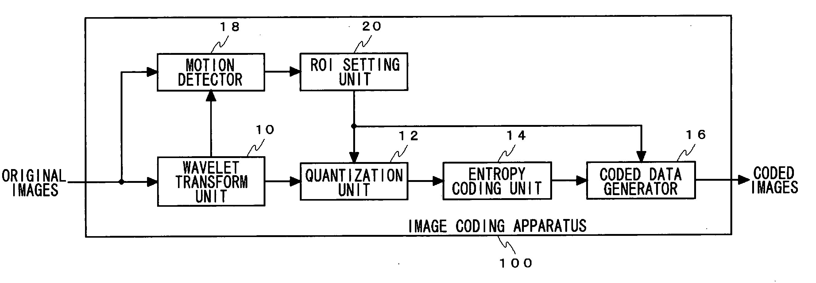
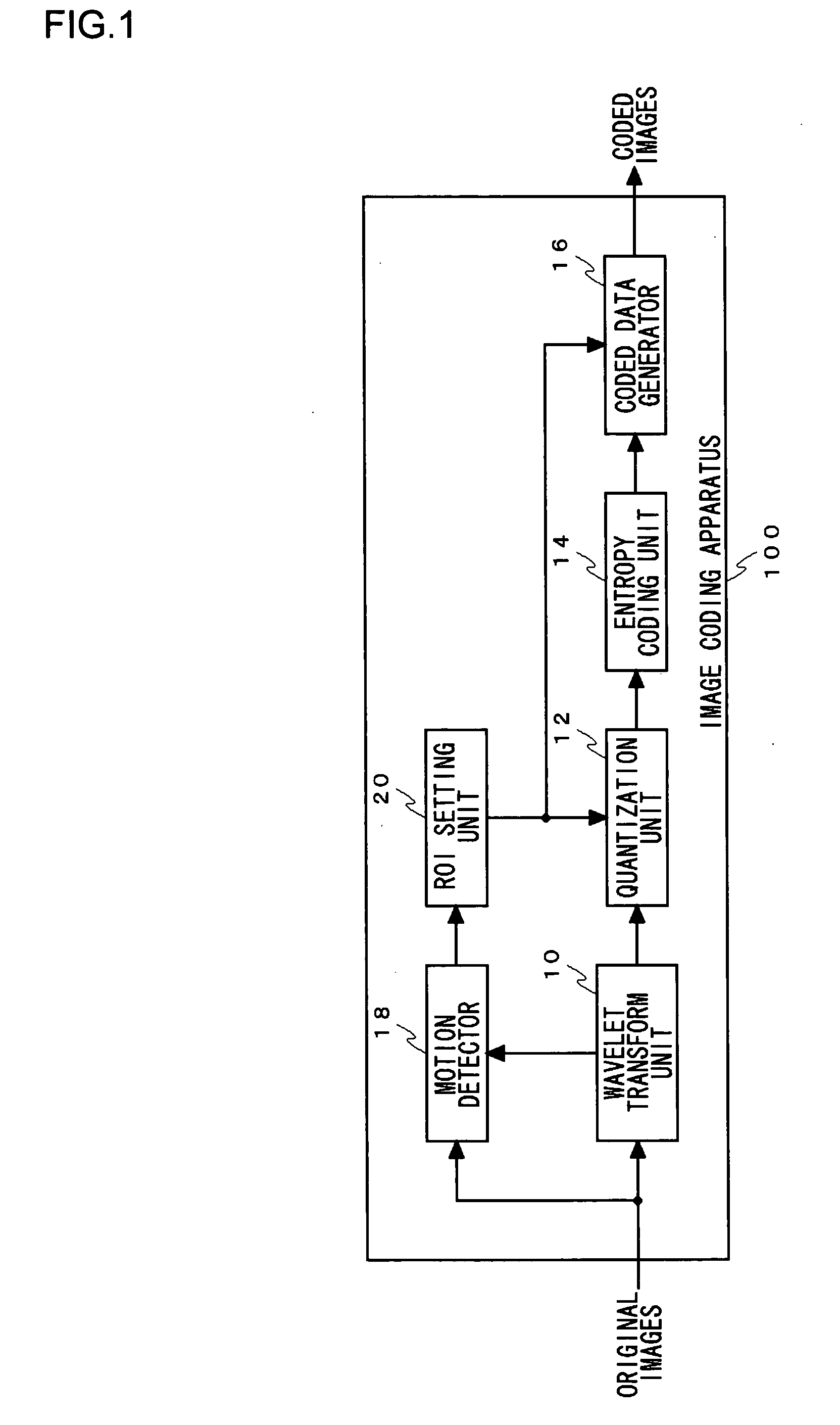
[0047]FIG. 1 illustrates a structure of an image coding apparatus 100 according to Embodiment 1 of a first embodiment. In terms of hardware, this structure of image coding apparatus 100 can be realized by a CPU, a memory and other LSIs of an arbitrary computer. In terms of software, it can be realized by memory-loaded programs which have coding functions or the like, but drawn and described herein are function blocks that are realized in cooperation with those. Thus, it is understood by those skilled in the art that these function blocks can be realized in a variety of forms such as by hardware only, software only or the combination thereof.

[0048] The image coding apparatus 100 performs compression and coding of inputted original images by, for example, JPEG2000 scheme. Original images inputted to the image coding apparatus 100 are frames of moving images. The image coding apparatus 100 encodes sequentially each frame of the moving images by the JPEG200 scheme so as t...

embodiment 4

[0093]FIG. 9 illustrates an image pickup apparatus 400 according to Embodiment 4 of the first embodiment. As examples of the image pickup apparatus 400, there are a digital camera, a digital video camera, a surveillance camera and so forth.

[0094] An image pickup unit 410 is provided with, for example, a CCD (Charge Coupled Device) or the like. The image pickup unit 410 takes in the light from a subject and converts it into electric signals so as to be outputted to a coding block 420. The coding block 420 encodes an original image inputted from the image pickup apparatus 410 and sends the coded image to an output unit 440.

[0095] The coding block 420 has a structure of any of image coding apparatus described in Embodiment 1 to Embodiment 3 in the first embodiment, and generates coded images such that the image quality thereof differs between a region of interest and a non-region-of-interest. An operating unit 430 includes a liquid crystal display, organic EL display or the like and ...

second embodiment

Embodiment 1

[0121]FIG. 13 illustrates a structure of an image decoding apparatus 1100 according to Embodiment 1 of a second embodiment. In terms of hardware, this structure of image decoding apparatus 1100 can be realized by a CPU, a memory and other LSIs of an arbitrary computer. In terms of software, it can be realized by memory-loaded programs which have decoding functions or the like, but drawn and described herein are function blocks that are realized in cooperation with those. Thus, it is understood by those skilled in the art that these function blocks can be realized in a variety of forms such as by hardware only, software only or the combination thereof.

[0122] In Embodiment 1 of the second embodiment, the image decoding apparatus 1100 decodes coded images which have been compressed and coded by, for example, JPEG2000 scheme. A coded image inputted to the image decoding apparatus 1100 is a normal coded image which has not been ROI-coded, where the ROI coding is such that ...


PUM


Abstract

A region of interest is set within an image, the region of interest is tracked along motion of an object marked out within the image, and coding is performed in a manner that image quality differs between the region of interest and a region other than the region of interest. A wavelet transform unit applies a low-pass filter and a high-pass filter in the respective x and y directions of an original image, and divides the image into four frequency sub-bands so as to carry out a wavelet transform. A quantization unit quantizes, with a predetermined quantizing width, the wavelet transform coefficients outputted from the wavelet transform unit. A motion detector detects the motion of an object. A ROI setting unit moves a ROI region according to this motion of an object. In the case of moving images where a viewpoint changes, the background may be separated from the object and then the ROI region may be moved according to the motion of the object and the motion of the background.

Description

BACKGROUND OF THE INVENTION [0001] 1. Field of the Invention [0002] The present invention relates to an image coding method, an image coding apparatus and an image pickup apparatus and it particularly relates to method and apparatus capable of coding images with different image qualities for each region as well as an image acquiring apparatus therefor. [0003] 2. Description of the Related Art [0004] At ISO / ITU-T, JPEG2000 using a discrete wavelet transform (DWT) is being standardized as a successor to JPEG (Joint Photographic Expert Group), which is a standard technology for compression and coding of still images. In JPEG2000, a wide range of image quality, from low bit-rate coding to lossless compression, can be coded highly efficiently, and a scalability function, in which the image quality is gradually raised, can be realized easily. Furthermore, JPEG2000 comes with a variety of functions which the conventional JPEG standard did not have. [0005] As one of the functions of JPEG200...

Claims


Application Information

Patent Timeline
Patent Type & Authority Applications(United States)
IPC IPC(8): G06K9/00H04N7/26
CPCH04N19/63H04N19/115H04N19/61H04N19/17H04N19/146H04N19/162H04N19/127
Inventor WATANABE, TSUYOSHIOKADA, SHIGEYUKI
Owner SANYO ELECTRIC CO LTD
Why Eureka
Try Eureka