Golf club head

a golf club and head technology, applied in the field of golf club head, can solve the problems of increasing dispersion, reducing distance, and reducing dispersion, and achieve the effect of improving mass distribution

Active Publication Date: 2005-12-29
CALLAWAY GOLF CO
View PDF57 Cites 31 Cited by
  • Summary
  • Abstract
  • Description
  • Claims
  • Application Information

AI Technical Summary

Benefits of technology

[0038] The present invention is generally directed to a golf club head that has improved mass distribution and optimized moments o

Problems solved by technology

Although this approach was effective in increasing the moments of inertia of the golf club heads, it also resulted in the center of gravity of the golf club head being positioned substantially rearward from the front face of the golf club head.
As the center of gravity is positioned further rearward from the front face, deleterious effects result for shots struck off-center from the sweet spot of the golf club head.
Increased gear effect is the main cause of the deleterious effects.
For heel-ward or toe-ward off-center hits, the increased gear effect can cause increased side-spin, which increases dispersion, reduces distance and reduces robustness of ball flight.
For off-center hits above the sweet spot, the increased gear effect causes reduced backspin, which can cause an undesirable trajectory having insufficient carry length or time of flight, which in turn can result in reduced distance and reduced robustness.
In addition, the same conventional golf club head designs are limited with regard to the maximum face area, both physical and practical limitations.
The physical limitation is due to the golf club head having insufficient mass t

Method used


Image

  • Golf club head
  • Golf club head
  • Golf club head

Examples


second embodiment

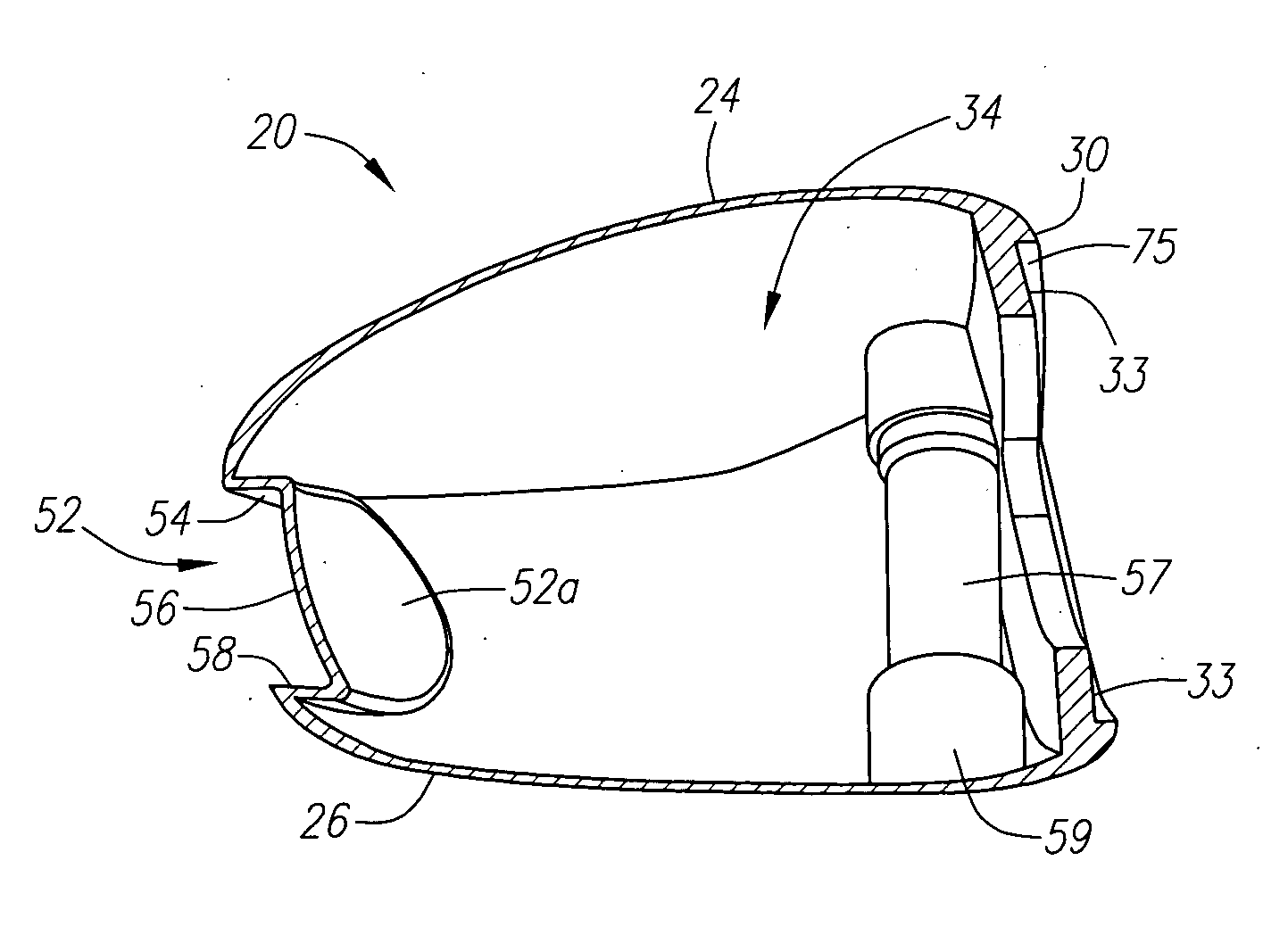
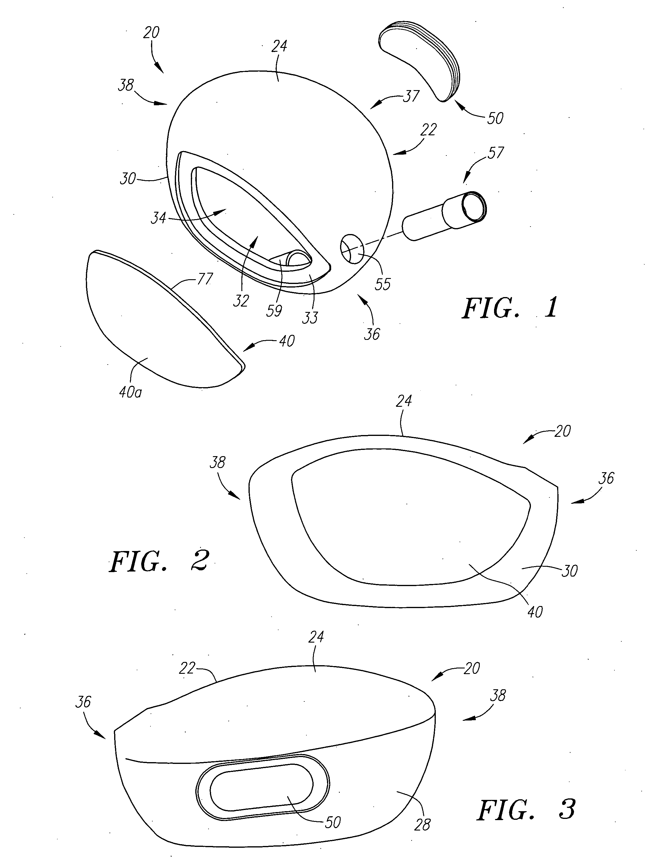
[0077] the golf club head 20 of the present invention is shown in FIG. 11. In this embodiment, the golf club head has a body 22 that is generally composed of a composite material such as continuous fiber pre-preg material (including thermosetting materials or thermoplastic material for the resin), other thermosetting materials such as thermosetting polyurethane, or other thermoplastic materials such as polyamides, polyimides, polycarbonates, PBT (polybutlene Terephthalate), blends of polycarbonate and the like. The body 22 is preferably manufactured through injection molding, bladder-molding, resin transfer molding, resin infusion, compression molding, or similar process.

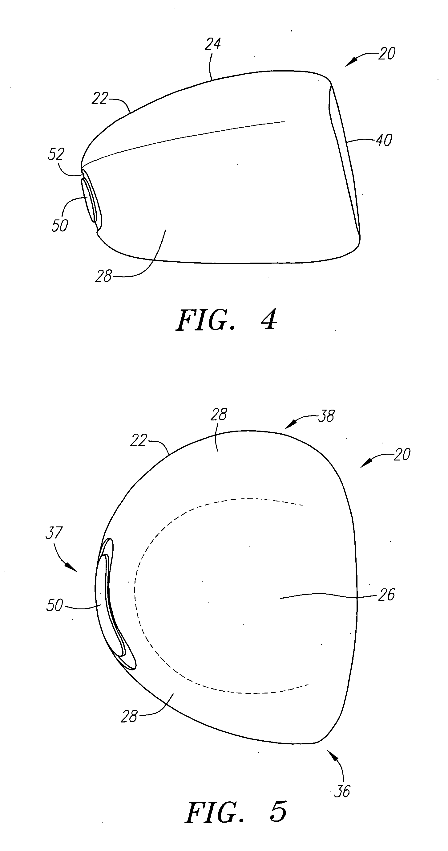
[0078] The body 22 includes a front wall 30, a sole 26, and a ribbon 28 that generally extends from a toe end 38 to a heel end 36. The ribbon 28 generally begins at one end of the front wall 30 and ends at an opposite end of the front wall 30. A rear 70 of the body 22 is opposite the front wall 30 and is defined by ...

third embodiment

[0084] the golf club head 20 of the present invention is shown in FIG. 12. In this embodiment, the golf club head 20 has a face component 60 and an aft-body 61. The aft-body 61 has a crown portion 62 and a sole portion 64. The club head 20 has a heel section 66 proximate the shaft 48, a toe section 68 opposite the heel section 66, and a rear section 70 opposite the face component 60. A hosel 57, not shown, is positioned within the hollow interior 34 of the club head 20 in the face component 60.

[0085] The face component 60 is generally composed of a composite material, such as a continuous fiber pre-preg material or other thermosetting or thermoplastic material. The face component 60 includes a front wall 30 and return portion 63. Like the body 22 in the second embodiment of the golf club head 20, shown in FIG. 11, the face component 60 includes a weight piece 46 preferably embedded therein, the weight piece 46 includes a striking plate insert 40 and return portion tabs 46c. The weig...

fourth embodiment

[0089] the golf club head 20 of the present invention is shown in FIGS. 13-15, such as disclosed in U.S. Pat. No. 6,565,452, for a Multiple Material Golf Club Head with Face Insert, filed on Feb. 28, 2002, and is hereby incorporated by reference in its entirety. In this embodiment, the golf club head 20, a face component 60 and an aft-body 61. The face component 60 has a face cup and has a separate striking plate insert 40, which is placed within an opening 45 of a face cup 74. The aft-body 61 has a crown portion 62 and a sole portion 64.

[0090] The face cup 74 has a return portion 63 that extends laterally rearward from the perimeter 73 of the front wall. The striking plate insert 40 is joined to the face cup 74 of the face component 60 in a manufacturing process discussed in co-pending U.S. application Ser. No. 10 / 710,143, entitled Method for Processing a Golf Club Head with Cup Shaped Face Component, filed on Jun. 22, 2004, and hereby incorporated by reference in its entirety.

[00...


PUM


Abstract

A golf club head (20) having optimized inertial properties and center of gravity is disclosed. The golf club head (20) preferably has a volume between 300 cubic centimeters and 500 cubic centimeters. The golf club head (20) has a center of gravity located less than 1.7 inches from an exterior surface of a front wall (30). The positioning of the center of gravity of the golf club head (20) and the optimized inertial properties provide the golf club with greater ball spin robustness and better performance.

Description

CROSS REFERENCE TO RELATED APPLICATIONS [0001] Not Applicable FEDERAL RESEARCH STATEMENT [0002] Not Applicable BACKGROUND OF INVENTION [0003] 1. Field of the Invention [0004] The present invention relates to a golf club head designed with optimized inertial properties and center of mass relative through the center of gravity. [0005] 2. Description of the Related Art [0006] As driver golf club heads have increased in volume (>300 cubic centimeters) their moments of inertia have also increased, providing greater forgiveness for offcenter hits. The conventional method for enlargement of golf club heads was to maximize the spatial distribution of mass in all three orthogonal orientations. Although this approach was effective in increasing the moments of inertia of the golf club heads, it also resulted in the center of gravity of the golf club head being positioned substantially rearward from the front face of the golf club head. [0007] As the center of gravity is positioned further r...

Claims


Application Information

Patent Timeline
IPC IPC(8): A63B53/04
CPCA63B53/0466A63B59/0088A63B2053/0408A63B2053/0412A63B2209/02A63B2053/0458A63B2053/0491A63B2209/023A63B2209/00A63B2053/0416A63B60/50A63B53/0412A63B53/0458A63B53/0408A63B53/0416A63B60/02
Inventor GALLOWAY, J. ANDREWHOCKNELL, ALANCACKETT, MATTHEW T.
Owner CALLAWAY GOLF CO
Why Eureka
Try Eureka