A gyro flywheel pair unbalance identification method

A technology of even unbalance and gyro flywheel, which is applied in the field of gyro flywheel even unbalance identification, can solve the problems of no-solution difference between different solutions, gyro flywheel even unbalance identification, etc., so as to improve torque output accuracy and attitude measurement accuracy, improve operation Stability, effect of improving mass distribution

Active Publication Date: 2021-02-09
HARBIN INST OF TECH
View PDF3 Cites 0 Cited by
  • Summary
  • Abstract
  • Description
  • Claims
  • Application Information

AI Technical Summary

Problems solved by technology

[0006] The purpose of the present invention is to propose a gyro flywheel couple unbalance identification method in order to solve the problem that the existing classical influence coefficient method will produce some no solutions and the large difference between different solutions

Method used


Image

  • A gyro flywheel pair unbalance identification method
  • A gyro flywheel pair unbalance identification method
  • A gyro flywheel pair unbalance identification method

Examples


specific Embodiment approach 1

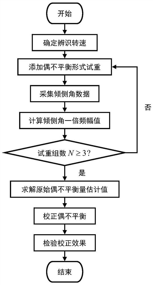
[0026] Specific implementation mode one: as figure 1 As shown, a gyro flywheel couple unbalance identification method includes the following steps:

[0027] Preliminary preparatory work to determine the specific process of the identification speed of the couple unbalance is as follows:

[0028] 1) Within the range of the working speed of the gyro flywheel, select the test speed as ω i , i=1,2,...,n;

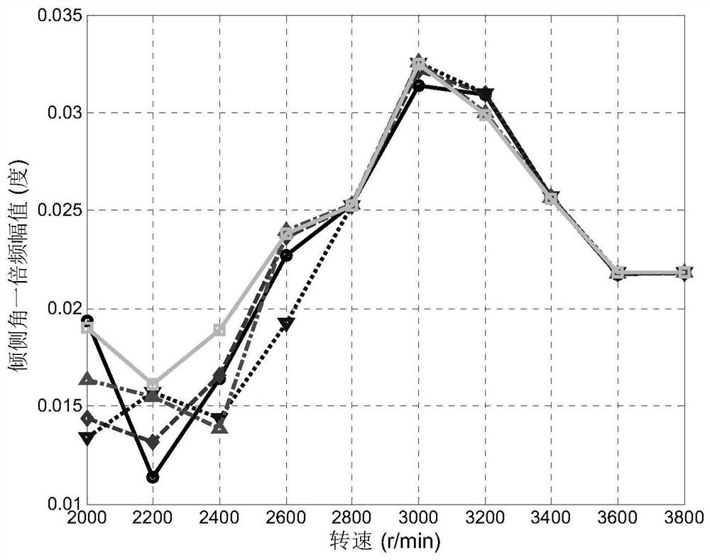
[0029] 2) When the test speed ω i After the operation is stable, make the gyro flywheel work in the open-loop state of the tilt control loop, record the data of the tilt angle of the gyro flywheel rotor within 10 seconds, and repeat this step 5 times;

[0030] 3) Using fast Fourier transform, calculate the inclination angle data collected in step 2), and obtain the 5 times of test speed ω i The corresponding one-octave amplitude of the roll angle is φ ij ,j=1,2,…,5, such as figure 2 shown.

[0031] 4) According to the amplitude φ of one octave frequency of the 5th roll a...

specific Embodiment approach 2

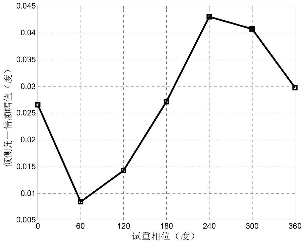
[0037] Specific embodiment 2: The difference between this embodiment and specific embodiment 1 is that in the step 1, a test weight in the form of even unbalance is added to the N phases of the rotor. Under the identification speed, the rotor tilt angle data is collected, and according to the tilt angle data Obtain the one-octave frequency amplitude of the inclination angle corresponding to the N phase addition trial weights as φ k The specific process is:

[0038] Step 11. Without adding any test weight, make the rotor of the gyro flywheel identify the speed ω T Stable operation, under the open-loop condition of the tilt control loop, record the gyro flywheel rotor tilt angle data within 10 seconds, use the fast Fourier transform to calculate the rotor tilt angle, and obtain the initial tilt angle double frequency amplitude as φ 0 ;

[0039] Step 1 and 2, in the gyro flywheel rotor phase θ k k=1,2,...,N,N≥3, N is the number of places to add test weight, and the added mass ...

specific Embodiment approach 3

[0043] Specific embodiment three: the difference between this embodiment and specific embodiment one or two is: in said step two, the N phase addition test weights obtained by step one are used to add the corresponding one-fold frequency amplitude of the roll angle to φ k , using the least squares estimation algorithm based on the amplitude influence coefficient method or the least squares estimation algorithm based on the amplitude and phase influence coefficient method, the specific process of identifying the original couple unbalance of the gyro flywheel rotor is as follows:

[0044] Step 21: Assume that the phase and amplitude of the original couple imbalance of the gyro flywheel are θ 0 and U 0 , the equivalent mass of the original couple unbalance on the test weight surface (the plane where the test weight is added) is m 0 . Based on the influence coefficient method, the complex number form is used to express the relationship between the inclination angle and the couple ...


PUM


Abstract

The invention discloses a gyro flywheel couple unbalance identification method. The gyro flywheel couple unbalance identification method is used for solving problems of conventional classical influence coefficient method that a part of unsolved situations are generated, and the difference between different solutions is large. The gyro flywheel couple unbalance identification method comprises following steps: 1, couple unbalance type trial mass is added to rotor N phase positions, under an identification rotating speed, rotor heeling angle data is collected, and a heeling angle twice frequencyamplitude value phi<k> corresponding to the N phase position added trial mass is obtained; 2, the heeling angle twice frequency amplitude value phi<k> corresponding to the N phase position added trialmass, and amplitude influence coefficient method-based least square estimation algorithm or least square estimation algorithm based on amplitude value and phase impact coefficient method are adopted,and identification of gyro flywheel rotor original couple unbalance is carried out; and 3, gyro flywheel couple unbalance calibration is carried out based on the results of the gyro flywheel rotor original couple unbalance identification results. The gyro flywheel couple unbalance identification method is used in the field of rotary machine dynamic balance.

Description

technical field [0001] The invention relates to the field of dynamic balance of rotating machinery, in particular to a method for identifying unbalance of a gyro flywheel couple. Background technique [0002] Combined with the characteristics of light weight, small size, low cost, short development cycle, easy technology update, high functional density, fast and flexible, and good maneuverability, the miniaturization of spacecraft has become the main focus and inevitable trend of space technology development. The attitude control system is one of the most important subsystems of a spacecraft, and it is the main contributor to the mass, volume, cost, and power consumption of a tiny spacecraft. Its lightweight implementation and multi-functional integration are important means to promote the development of tiny spacecraft. [0003] The gyro flywheel is a new type of attitude control and attitude sensitive device. It integrates the functions of the variable-speed double-frame c...

Claims


Application Information

Patent Timeline
Patent Type & Authority Patents(China)
IPC IPC(8): G01C25/00G01M1/38
Inventor 霍鑫刘海媛皮永江郭照升冯四兆赵辉
Owner HARBIN INST OF TECH
Why Eureka
Try Eureka