Producing a rotor by means of additive manufacturing

A rotor and rotor core technology, applied in the field of short-circuit rings, can solve problems such as the inability to realize the material gradient of short-circuit rings, and achieve the effects of improving efficiency and performance, helping cooling, and high speed

Active Publication Date: 2019-11-01
SIEMENS AG
View PDF7 Cites 0 Cited by
  • Summary
  • Abstract
  • Description
  • Claims
  • Application Information

AI Technical Summary

Problems solved by technology

Furthermore, a material gradient in the short-circuit ring cannot be realized, in which there is a progression from copper

Method used


Image

  • Producing a rotor by means of additive manufacturing
  • Producing a rotor by means of additive manufacturing
  • Producing a rotor by means of additive manufacturing

Examples


Embodiment Construction

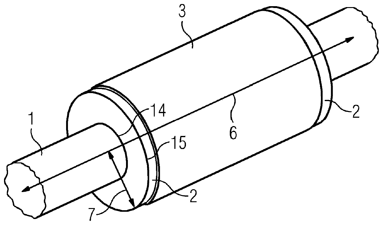
[0039] figure 1 One configuration of a rotor connected to the shaft 1 is shown, the rotor having a rotor core 3 and correspondingly short-circuiting rings 2 at its axial ends. Furthermore, the axial direction 6 and the radial direction 7 are shown, as well as the inner radius 14 and the outer radius 15 of the short-circuit ring. Preferably, the rotor is designed as a squirrel-cage rotor and the rotor comprises squirrel-cage bars extending in the axial direction 6 or substantially obliquely in the axial direction 6 and short circuits at the axial ends of the squirrel-cage bars Ring 2, which shorts the squirrel cage rods. According to the present invention, only the cage rods or the short-circuit rings 2 , or the cage rods and the short-circuit rings 2 can be produced by the MPA method. Advantageously, the squirrel cage bars are prefabricated, preferably from copper or aluminum, and inserted into the rotor core 3, and the short-circuit rings 2 are then added by the MPA method....


PUM


Abstract

The invention relates to a method for producing a rotor of an electric machine, which rotor is preferably designed as a squirrel-cage rotor. The end rings and/or squirrel-cage bars are produced by means of a metal powder application method. The invention further relates to an end ring for a rotor of an electric machine, said end ring in particular being produced by means of said method.

Description

technical field [0001] The invention relates to a method for manufacturing a rotor of an electric machine, wherein the rotor has a rotor core arranged concentrically with respect to the rotor axis, wherein the rotor core has grooves, and wherein the rotor cores at respective axial ends of the grooves are respectively There is an annular recess arranged concentrically with respect to the rotor axis, which connects the grooves. Furthermore, the invention relates to a short-circuit ring for a rotor of an electric machine, produced in particular by such a method. Background technique [0002] To date, various methods have been used for the production of short-circuit cages for rotors of asynchronous machines, wherein the short-circuit cages comprise cage rods in the rotor laminations and short-circuit rings at the lamination ends. [0003] Squirrel cage rods and shorting rings are cast by copper die-casting process. [0004] In another known method, prefabricated copper rods a...

Claims


Application Information

Patent Timeline
IPC IPC(8): H02K15/00H02K17/16H02K17/20H02K3/02
CPCH02K17/165H02K3/02H02K15/0012H02K17/20
Inventor 克劳斯·比特纳赖纳·索伊弗特拉尔夫·福尔默
Owner SIEMENS AG
Why Eureka
Try Eureka