Built-in piezoelectric-type online dynamic balance actuator

a dynamic balance actuator and piezoelectric technology, applied in the field of spindle balancing technology, can solve the problems of increasing the complexity of the device, limiting the transmission accuracy of the device, and the limitations of the existing online balancing terminal, so as to reduce the volume and weight, and reduce the running speed

Active Publication Date: 2021-01-26
XI AN JIAOTONG UNIV
View PDF5 Cites 0 Cited by
  • Summary
  • Abstract
  • Description
  • Claims
  • Application Information

AI Technical Summary

Benefits of technology

[0009]The vibration of the first stator 8 and the second stator 28 is generated by piezoelectric ceramic excitation, which is triggered by a two-phase excitation voltage of a control center, the right weight mass 5 and the left weight mass 25 are arranged to be driven by the control center to form a preset angle and then centrifugal force generated by the right weight 5 and the left weight 25 during high speed rotational movement of the main shaft combine to form a balance vector to cancel the imbalance vector of the main shaft so that mass distribution of the main shaft is improved.
[0017]Compared with the existing arts, the present invention has the following advantages:
[0018]1. The present invention employs the piezoelectric driving technology, which has low running speed and does not need an intermediate reduction transmission mechanism, thereby simplifying the structure, reducing the volume and weight, improving the driving precision while having fast dynamic response, good control performance and the micro-displacement characteristic, which is very suitable for mass position adjustment and positioning control.
[0019]2. Since the present invention does not include electromagnetic coil, neither magnetic field nor magnetic field interference is generated, thus electromagnetic pollution is greatly reduced while the reliability of the device of the present invention under a harsh environment is also improved.
[0020]3. The present invention is installed in the central shaft hole of the hollow main shaft through a transition fit, and does not interfere with the installation of the grinding wheel or the cutter at the main shaft end, thereby minimizing the influence on the main shaft structure.

Problems solved by technology

However, the existing online balancing terminals have some limitations, especially in the field of high-speed grinding machines.
First, the advantage of the motor-driven balancing terminal is that it is easy to implement, but since the brushless motor itself lacks self-locking capability and has a high rotational speed, it is necessary to add a self-locking mechanism and a speed reduction mechanism in the balancing terminal, which not only increases the complexity of the device, but also limits the transmission accuracy of the device.
However, the mechanical structure and control system are relatively complicated, the self-locking capability is also not high, the balance ability is relatively small, and when the temperature is too high, the permanent magnet is easily demagnetized and interfered by strong magnetic field.
However, its balance accuracy is affected by the combined effect of the shape of the cavity and the accuracy of the liquid beam control.
In the high-precision balance, it is necessary to properly design the balance terminal structure and hydraulic system parameters, and there exists too many interference factors in industrial field applications.
The last type standing wave type piezoelectric online dynamic balancing device avoids some of the above problems, but due to some problems in the structure of the existing standing wave type piezoelectric online dynamic balancing device, the standing wave type also has a serious problem of friction and wear.
The end-type linear balancing device has a certain interference in the space for the normal operation of the machine tool.

Method used


Image

  • Built-in piezoelectric-type online dynamic balance actuator
  • Built-in piezoelectric-type online dynamic balance actuator
  • Built-in piezoelectric-type online dynamic balance actuator

Examples


Embodiment Construction

[0026]The present invention is further described in detail with reference to the accompanying drawings and embodiments as follows.

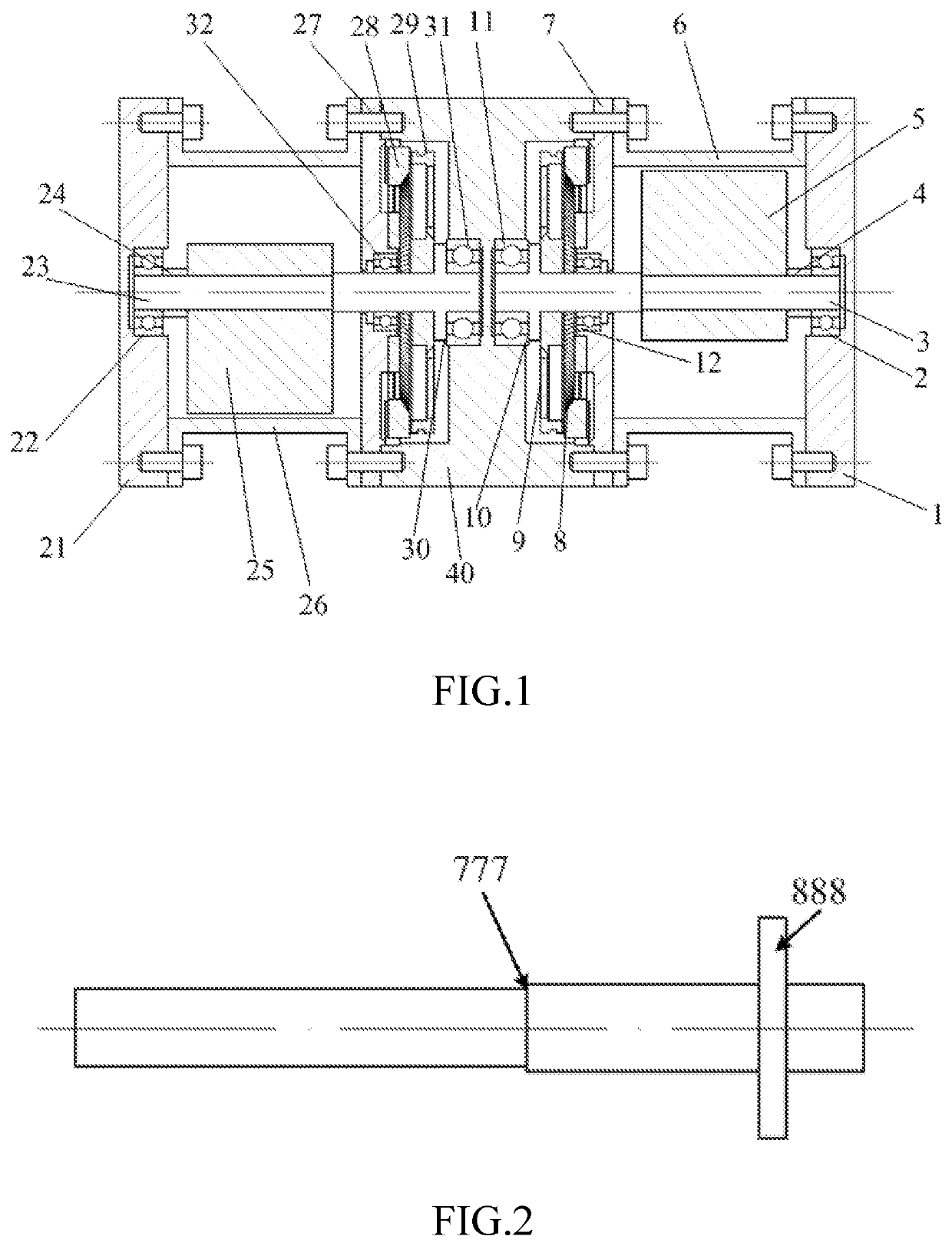
[0027]Referring to FIG. 1, FIG. 2, FIG. 3, FIG. 4 and FIG. 5 of the drawings, a built-in piezoelectric type online dynamic balance actuator comprises a housing 40, a left piezoelectric drive adjustment mechanism and a right piezoelectric drive adjustment mechanism connected to two sides of the housing 40. The left piezoelectric drive adjustment mechanism and the right piezoelectric drive adjustment mechanism have the same structure and are completely symmetrical in structure.

[0028]The right piezoelectric drive adjustment mechanism includes a right shaft 3. A front end of the right shaft 3 is supported in a right chamber of the housing 40 through a third bearing 11, a middle portion of the right shaft 3 is connected to a right end cover 7 through a second bearing 12, and a rear end of the right shaft 3 is supported on a right bearing housing 1 through a fi...


PUM


Abstract

A built-in piezoelectric type online dynamic balance actuator which includes two structurally identical left and right piezoelectric drive adjustment mechanisms at two sides of a housing. The piezoelectric drive adjustment mechanism includes a shaft having one end supported inside a housing chamber by bearing, a middle portion connected to an end cover by bearing, and the other end supported on bearing housing by bearing, a weight mass coupled to the shaft and positioned inside a tightening sleeve with one side connected to the bearing housing and another side connected to the end cover and the housing, and a stator fixedly connected to one side of the end cover, a mover pressed against a surface of the stator through a disk. Through a control center, the mass weights of the left and right piezoelectric drive adjustment mechanisms are fixed to a preset angle. As the main shaft rotates at a high speed, the two weight masses generate centrifugal force which combine to a balance vector to cancel the imbalance vector of the main shaft, improve the mass distribution of the main shaft and better fit the online dynamic balance requirements.

Description

BACKGROUND OF THE PRESENT INVENTIONField of Invention[0001]The present invention relates to the spindle balancing technology, and more particularly to a built-in piezoelectric-type online dynamic balance actuator.Description of Related Arts[0002]The high precision and high efficiency requirements of modern machining have placed high demands on CNC machine tools. As the core functional component of the machine tool, the spindle will directly affect the machining level of the machine tool. With the development of technology, online dynamic balance technology for quality correction through balancing terminals has been developed, and gradually achieved good results in the application process, which can better solve the problems of on-site dynamic balance technology. There are three main ways to realize the online suppression of spindle vibration by using the balancing terminal for mass redistribution: (1) Motor-driven type: this type uses a permanent magnet motor or a DC brushless motor...

Claims


Application Information

Patent Timeline
Patent Type & Authority Patents(United States)
IPC IPC(8): H02N2/12H01L41/04
CPCH02N2/12H01L41/042H02N2/163F16F15/223F16F2224/0283H10N30/802
Inventor MEI, XUESONGYUN, XIALUNJIANG, GEDONGDENG, JIACHUNTAO, TAOXU, MUXUN
Owner XI AN JIAOTONG UNIV
Why Eureka
Try Eureka