Transmission control method for increasing engine idle temperature

Active Publication Date: 2005-12-29
GM GLOBAL TECH OPERATIONS LLC
View PDF13 Cites 25 Cited by
  • Summary
  • Abstract
  • Description
  • Claims
  • Application Information

AI Technical Summary

Benefits of technology

[0003] The present invention is directed to an improved method of operation for a motor vehicle powertrain including an internal combustion engine coupled to a power transmission through a fluid coupling, where a friction device of the transmission controls the state of the fluid coupling during neutral idle operation of the engine for increasing the engine temperature to a desired level. The fluid coupling includes an input member connected to t

Problems solved by technology

While the heat generated during normal vehicle operation is sufficient for these purposes, the heat generated during idle operation can be insufficient, particularly during extended idle operation of a die

Method used


Image

  • Transmission control method for increasing engine idle temperature
  • Transmission control method for increasing engine idle temperature
  • Transmission control method for increasing engine idle temperature

Examples


Embodiment Construction

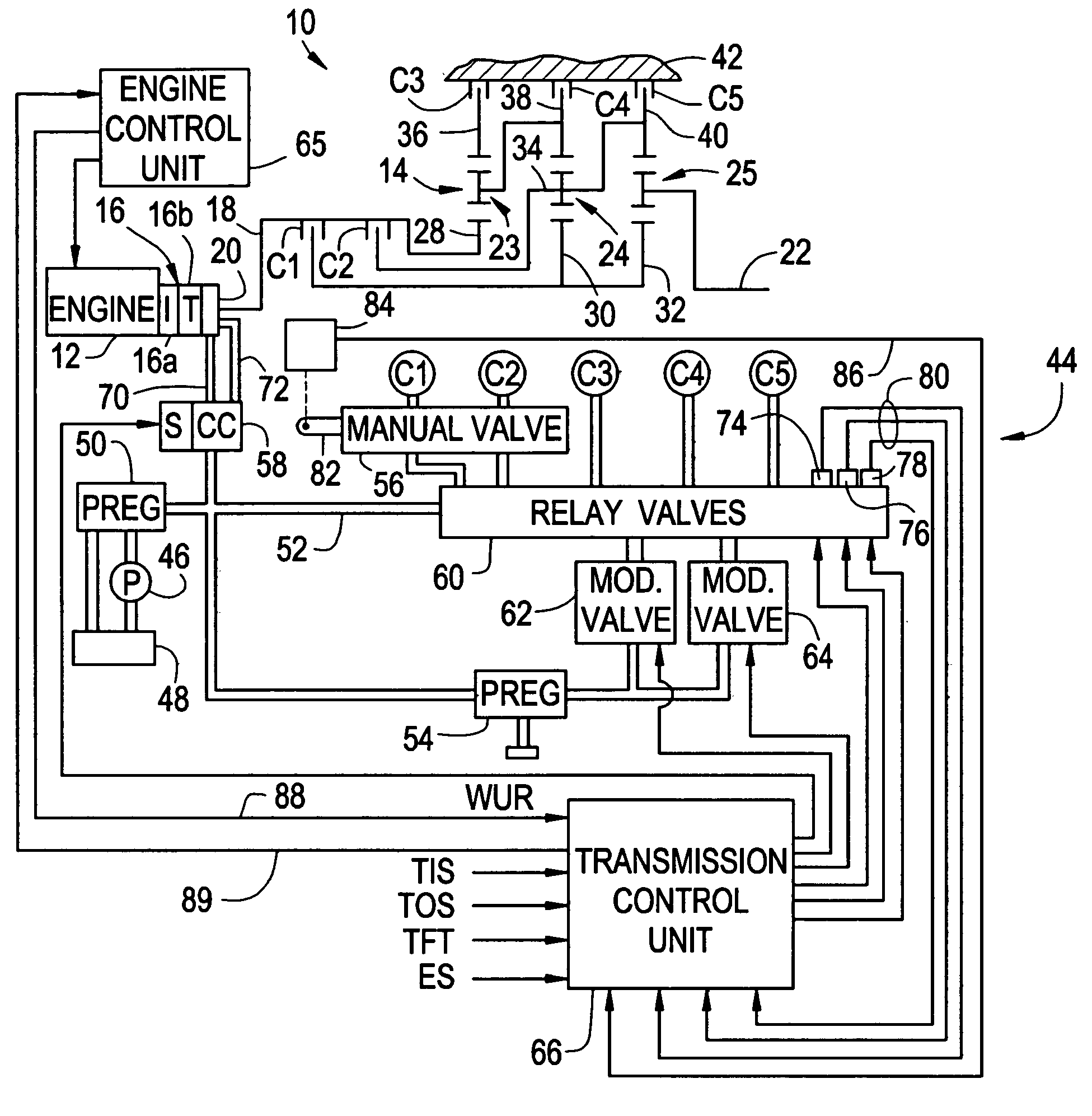
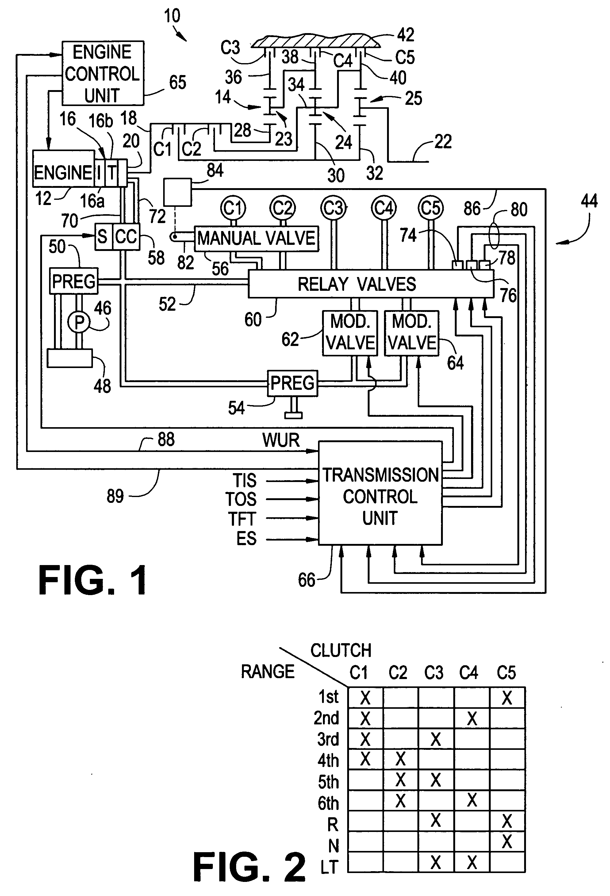
[0008] Referring to FIG. 1, the method of the present invention is disclosed herein in the context of a motor vehicle powertrain 10 including a diesel engine (ENG) 12 and a multi-ratio power transmission 14 having a planetary gearset of the type described in the U.S. Pat. No. 4,070,927 to Polak and an electro-hydraulic control of the type described in U.S. Pat. No. 5,601,506 to Long et al., such patents being incorporated herein by reference. Accordingly, the gearset and control elements shown in FIG. 1 hereof have been greatly simplified, it being understood that further detail regarding the fluid pressure routings and so forth may be found in the aforementioned patents.

[0009] The engine 12 is coupled to the transmission 14 through a fluid coupling such as the torque converter 16. An input member or impeller (I) 16a of the torque converter 16 is connected to an output shaft of the engine 12 and an output member or turbine (T) 16b of the torque converter 16 is connected to an input...


PUM


Abstract

The state of a fluid coupling in a motor vehicle powertrain is selectively controlled during neutral idle operation of the engine for increasing the engine temperature to a desired level. The fluid coupling includes an input member connected to the engine and an output member connected to the transmission, and the output member is selectively grounded under specified enable conditions to impose an engine load for raising the engine operating temperature. The output member is released to resume normal operation of the powertrain when the enable conditions are no longer met or an estimate of the fluid temperature in the coupling reaches or exceeds a predefined temperature.

Description

TECHNICAL FIELD [0001] The present invention relates to the control of a motor vehicle powertrain including an internal combustion engine coupled to a power transmission through a fluid coupling, and more particularly to a transmission control for selectively increasing the engine temperature during idle. BACKGROUND OF THE INVENTION [0002] In most motor vehicle powertrains, the heat generated due to operation of the engine is advantageously utilized, not only for cabin heating, but also for heating various exhaust gas emission control devices such as catalytic converters and particulate traps. While the heat generated during normal vehicle operation is sufficient for these purposes, the heat generated during idle operation can be insufficient, particularly during extended idle operation of a diesel engine. As a result, warming up the cabin during cold ambient temperatures can take an undesirably long time, and the exhaust gas temperature may be insufficient to activate the emission ...

Claims


Application Information

Patent Timeline
IPC IPC(8): F02D41/08F16H59/64F16H59/78F16H61/00F16H61/02
CPCB60W2710/065Y10T477/647F01P2060/045F02D41/0225F02D41/068F02D41/083F02D41/086F02D2041/026F02D2200/502F02D2250/24F02D2400/12F16H59/78F16H61/0202F16H2061/0018Y10T477/6343Y10T477/653Y10T477/634F01P2037/02
Inventor HITCH, RONALD P.KLUEMPER, KEVIN L.
Owner GM GLOBAL TECH OPERATIONS LLC
Why Eureka
Try Eureka