Blood clot filter

a filter and vena cava technology, applied in the field of permanent vena cava filter device, can solve the problems of thrombosis and buildup at and around the filter, the majority of the ivc filter presently on the market does not meet other desirable characteristics, and the filter cannot be positioned within the vessel, so as to achieve low manufacturing cost, high structural integrity, and low profile

Inactive Publication Date: 2005-12-29
ANGIODYNAMICS INC
View PDF5 Cites 52 Cited by
  • Summary
  • Abstract
  • Description
  • Claims
  • Application Information

AI Technical Summary

Benefits of technology

[0017] Various aspects of the present blood clot filter design provide high structural integrity, low manufacturing cost, symmetrical deployment of the filter struts, low profile and stable centering of the filter section.

Problems solved by technology

Although addressing some desirable characteristics of a filter, the majority of the IVC filters presently on the market do not satisfy other desirable characteristics of an ideal filter.
Unfortunately, many filters are designed for ease of deployment but they either do not remain aligned within the vessel or have sub-optimal filtering capabilities.
Blood flow disruption and turbulence often leads to thrombus formation and buildup at and around the filter.
Although conical filter configurations currently available on the market provide optimal filtering capabilities, these designs are prone to tilting and misalignment.
When not in proper alignment, filtering ability is compromised.
Misalignment can also lead to filter leg crossing, vessel perforation and migration of the device due to incomplete vessel wall engagement.
Laminar blood flow is disturbed, effective lysing of captured clots decreases, and thrombus build-up occurs.
This design, while exhibiting increased stability, is not practical due to the increased length of the device.
Longer lengths are undesirable because of the limited implantation space of the vena cava.
For example, in some cases it is necessary to deploy a second filter due to malfunction of the initially placed filter.
Shortening the filter segment may make the overall device length acceptable, but may result in sub-optimal filter strut angles.
Alternatively, shortening the centering cage segment may compromise the alignment function of the device.
Although rare, filters can develop fractures which have potentially fatal complications including filter migration into the right atrium and pulmonary embolism caused by compromised filtering efficiency.

Method used


Image

  • Blood clot filter
  • Blood clot filter
  • Blood clot filter

Examples


Embodiment Construction

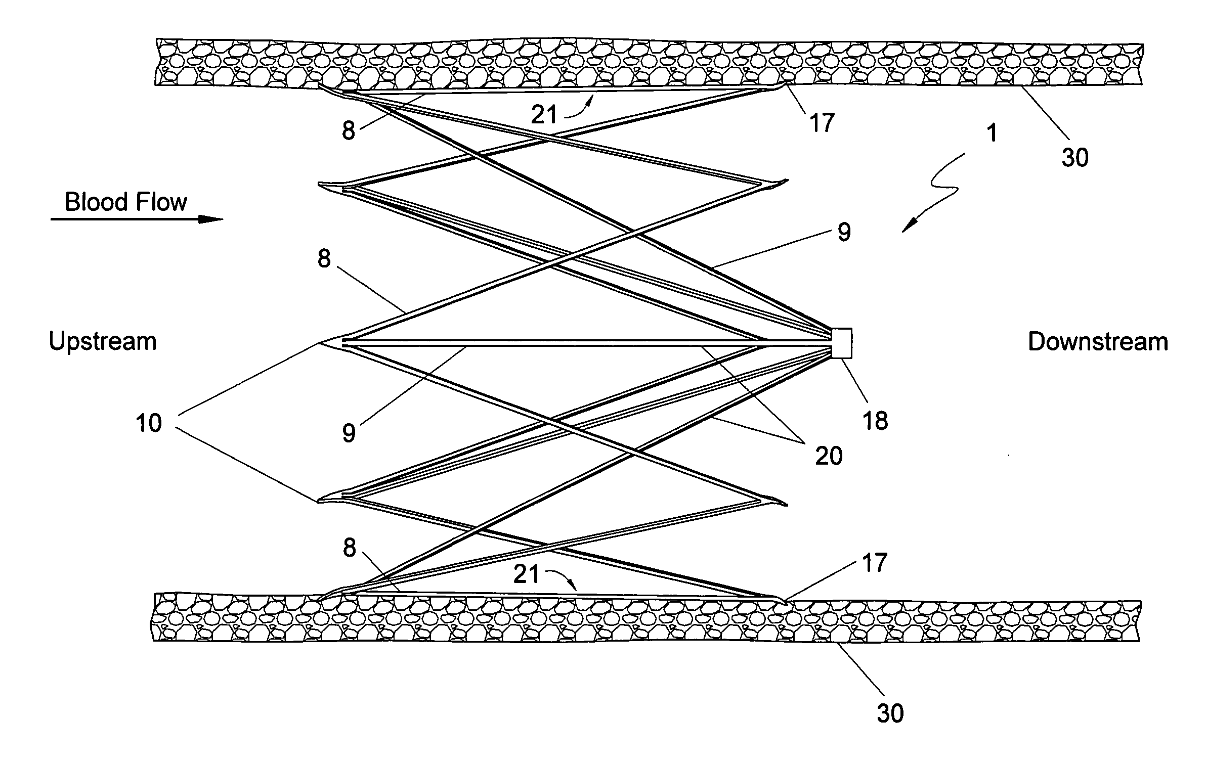
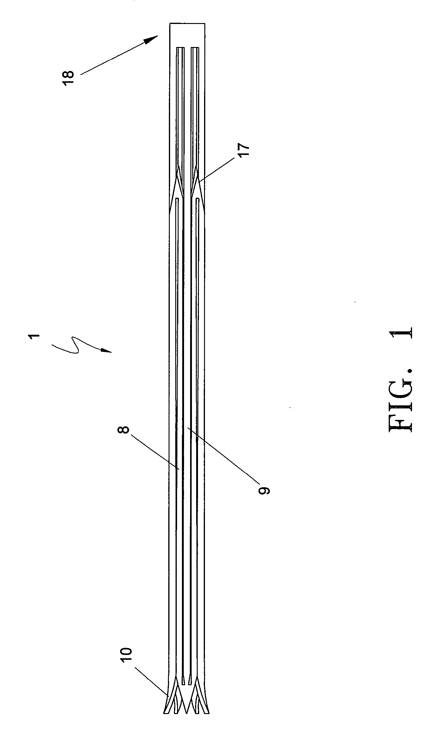
[0024] For purposes of the present application, the terms upstream and downstream refer to the direction of blood flow. Accordingly, blood flows from the upstream direction towards the downstream direction. Referring to FIG. 1, the vena cava filter of the present invention is shown from a plan view in a non-expanded undeployed state. The filter 1 includes a slender tubular construct 1 that can be percutaneously inserted through a catheter (not shown) into a patient. The tube is preferably of a material with shape-memory characteristics such as nitinol to allow self-expansion from the non-expanded collapsed state shown in FIG. 1. Nitinol is an alloy well suited for vena cava filters because of its superelastic characteristics, which enable it to return to a pre-determined expanded shape upon release from a constrained position. Other memory materials including stainless steel may be used.

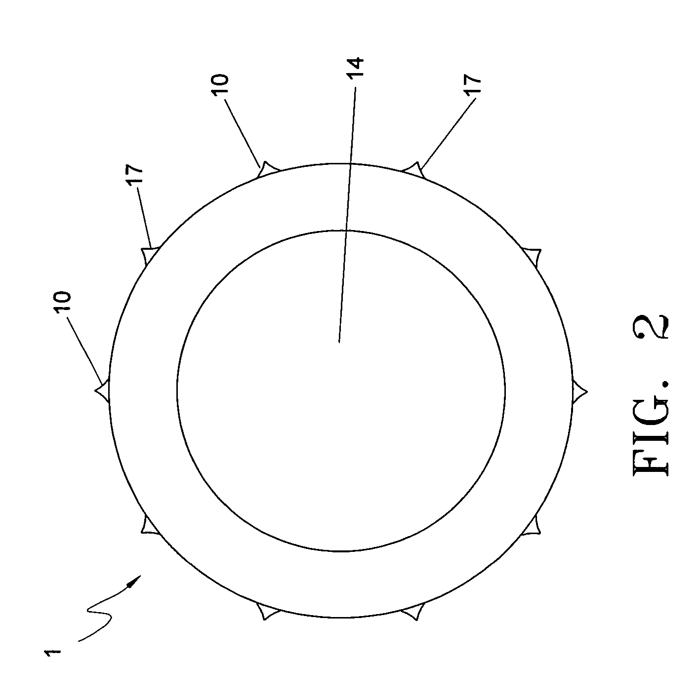
[0025] Manufacturing the device involves cutting the tube into a desired configuration using las...


PUM


Abstract

A compact blood clot filter having an alignment section that overlaps with a filter section in an axial direction is formed from a single tube without any welding points to provide high structural integrity, low profile and low manufacturing cost. The filter section has filter struts that extend radially and longitudinally from a hub. The alignment section has alignment struts in which the downstream end of each alignment strut forms a junction with the downstream end of an adjacent alignment strut while the upstream end of each alignment strut forms a junction with the upstream end of an adjacent alignment strut and with one of the filter struts to ensure symmetrical deployment of the filter struts and provide stable centering of the filter section.

Description

CROSS REFERENCE TO RELATED APPLICATIONS [0001] This application claims priority under 35 U.S.C. §119 (e) to U.S. provisional patent applications, Ser. No. 60 / 583,274, filed Jun. 25, 2004 and 60 / 614,757, filed Sep. 29, 2004, all of which are hereby incorporated by reference.FIELD OF THE INVENTION [0002] The present invention relates to a medical device and method for the capturing of thrombus. More particularly, the present invention relates to a permanent vena cava filter device for the capture of blood clots and method of manufacturing the same. BACKGROUND OF THE INVENTION [0003] Vena cava filters are used to capture potentially fatal pulmonary emboli at an anatomical location where they may pose less risk of pulmonary embolism for a patient. Since the vast majority of pulmonary emboli originate from the lower body, filters are mainly placed in the inferior vena cava (IVC). [0004] Vena cava filters have been in use since the 1960s in a variety of configurations. Early filters requi...

Claims


Application Information

Patent Timeline
Patent Type & Authority Applications(United States)
IPC IPC(8): A61F2/01A61M29/00
CPCA61F2/01A61F2230/0067A61F2230/005A61F2002/016A61F2/0103A61F2/0105
Inventor BEYER, THEODOREPALMA, GIORGIO DICARTIER, WILLIAM A.
Owner ANGIODYNAMICS INC
Why Eureka
Try Eureka