
Medical device for treating skin problems

Inactive Publication Date: 2005-12-29
LI HUAN CHEN +1
View PDF6 Cites 108 Cited by
  • Summary
  • Abstract
  • Description
  • Claims
  • Application Information

AI Technical Summary

Benefits of technology

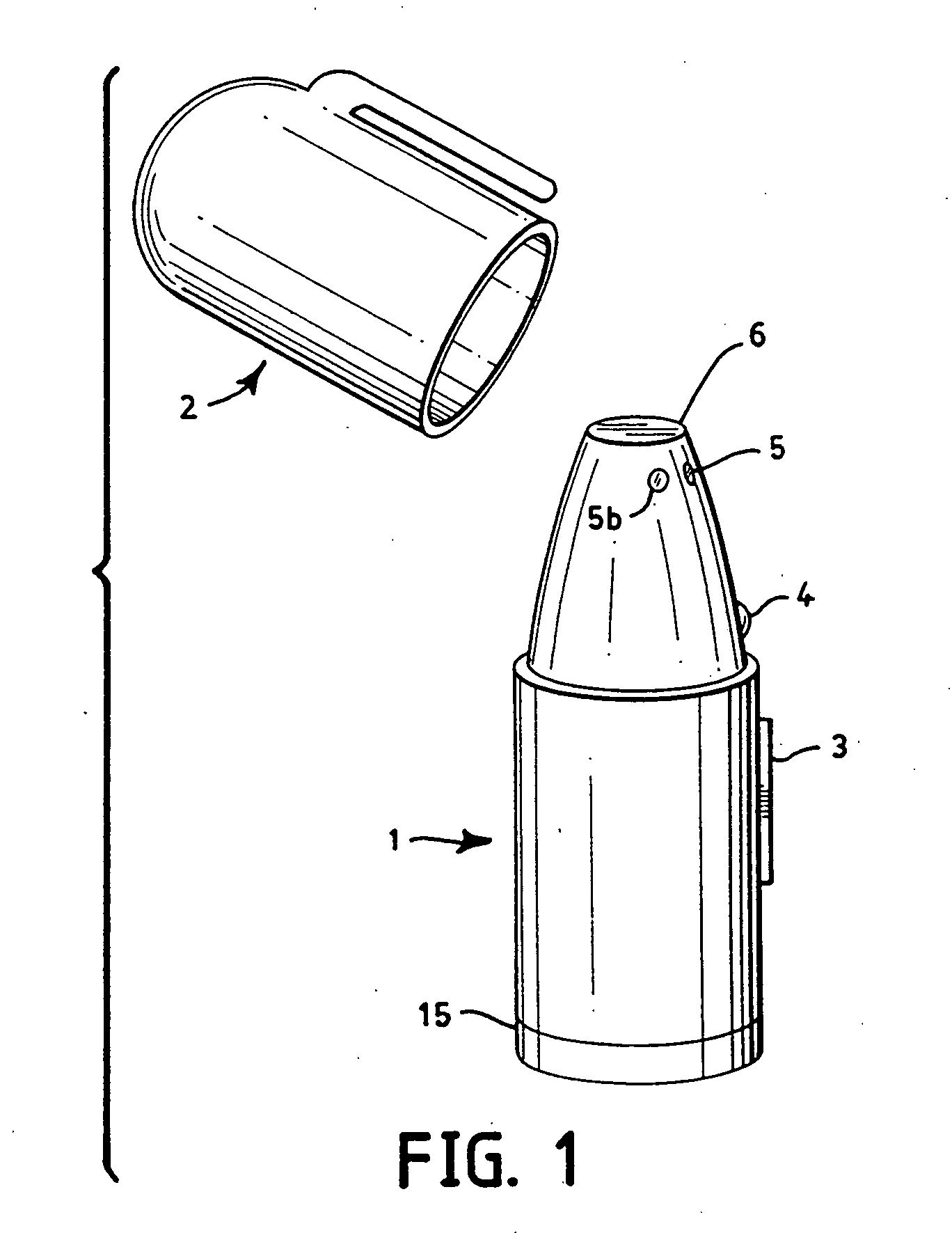
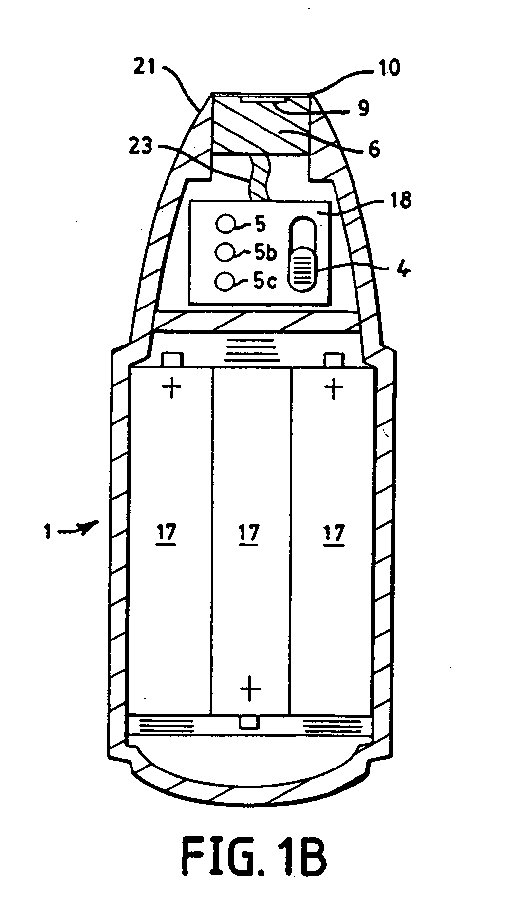
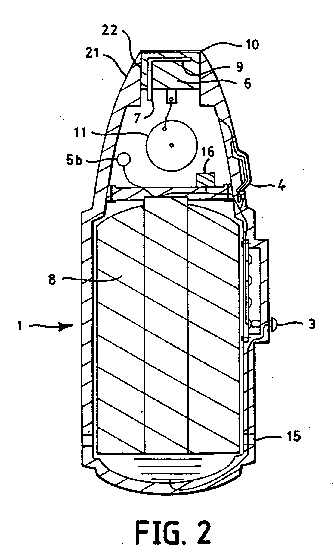
[0020] The invention is to make an heating apparatus work on skin itching and problems. Our apparatus has two unique features. First, the apparatus can provide a specific temperature such as 50° C. Second the temperatures is substantially unique which means its variation is so narrow as to work for a unique case. It is a further object of this invention to provide such an apparatus which is simple, inexpensive, and portable.
[0026] According to a fifth aspect of the invention, the positioning and selection means provide a periodic motion of the heating surface, and the selection means provides control of frequency and duty cycle of said motion.

Problems solved by technology

Since UV can also cause DNA damage, skin-cancer and skin aging, it is not the ideal means to activate stress-genes.
However, the use of heat in the treatment of skin itch and rash is different from such treatment for other skin problems.
These toddlers will not allow you to apply such a heat, in the case of a metal heater, for a enough time, such as for at least 1-2 seconds, that is required for heat the dermis to the effective temperature, therefore, mast cells cannot be inactivated and the itch will be worsen.
If 50° C. is used for adult leg skin that is thicker than the face skin, the itch will not be stopped and side effects, such as edema and rebound of itch, may result.
However, none of these is effective against skin itch and rash, because none of them accurately and precisely apply the required temperatures for treating itch and rash.
They have to provide temperatures not significantly higher than 43° C., otherwise, they will cause burning.
This method obviously can not be done with the amount of control required to effect the best effective temperature, or with control of the time of application.

Method used


Image

  • Medical device for treating skin problems
  • Medical device for treating skin problems
  • Medical device for treating skin problems

Examples


third embodiment

[0053] The third embodiment as shown in FIG. 4 that omits the positioning means 11 and the grid 10 of the above mentioned embodiment. In this case, a light indicator 5 that will be turned on or will flash or will change color after the heater reaches the selected temperature will be include in this apparatus to replace the omitted elements 10 and 11 to ensure only said best effective temperature is used. Also in this case said heater is fixed at said contact end and said intermittent application of heat is performed manually it would be possible to omit the light indicator 5 if a strong and stable power source, together with a good heat-transfer material for the heat transfer surface are used, providing rapid heating of the transfer surface to the desired temperature, and maintaining of that temperature.

[0054] The fourth embodiment as omits the temperature selector of the second embodiment. In this embodiment the heater is fixed at one exact best effective temperature, selected for ...

fifth embodiment

[0055] In a fifth embodiment, as shown in FIG. 5, a heat-conducting liquid is used to maintain the temperature within the heat transfer surface which contacts the user's skin. The liquid used is preferably one with a high specific heat, such as oils of various types. The material need not be liquid at room temperature, so long as it liquefies at the best effective temperature. The advantage of this method is that the temperature and the sensing device may be located at any point within the liquid, or in proximity to the liquid, simplifying the design and manufacture of the apparatus. The high specific heat of the liquid, as well as the mobility of the molecules within the liquid, produces a uniform temperature within the body of the liquid. In contrast, metals may exhibit a thermal gradient between the area in proximity with the heater and the area in proximity with the skin, making accurate temperature control more difficult. Referring to FIG. 75, the heating element 6 is immersed ...

sixth embodiment

[0057] In a sixth embodiment, as shown in FIG. 6, laser, microwave, sonic sound, and infrared radiation may also be used as a heat source for this invention. Such indirect heat sources require special means to detect heat at the surface of the skin. One recommended method is to incorporate the temperature transducer in a grid 10 located at the contact end of the apparatus, as shown in FIG. 6, which depicts a sixth preferred embodiment of the invention. In this case, the heater source will be set behind the opening at the contact end. The heater should provide a heating energy that is high enough to heat the skin to an effective temperature within about 1-10 seconds. A wall means, such as a grid FIG. 7, item 12, that is made of thin wires, with holes allowing the energy to pass directly to the skin, is located at this opening to prevent direct contact of the skin to the heat source 6, as will as to prevent the user from accidentally placing his fingers, or other objects, in contact w...


PUM


Abstract

An apparatus and method that is effective for the treatment of skin itch and skin rash is disclosed. The apparatus is contained within a body which can be easily manipulated with one hand, and which is powered by a self-contained battery. Also contained within the body is a heating means, controlled by a thermostat, a temperature selector if the heating means if intended to provide multiple temperatures, and means to warn the user when the desired temperature is reached. In addition the apparatus includes means to apply the heat in a cyclical manner, in which the heat is repeatedly applied and removed, with a cycle time and pulse width in which is controlled by user by means of a control located on the body heater and some other elements that can ensure only one substantially unique temperature is used. The method, which is related to the apparatus as its governing principle, includes the application of heat at a precise, controlled temperature, for a specific period of time, t the skin at the location of the itch or rash. The temperature used depends upon the nature of skin discomfort, but is generally inside the range between 46-62° C. The temperature variation is generally controlled within ±0.5° C. although it can be wider or narrower depends upon the nature of the itch treatment. In addition, the method includes a pulsating application of heat to the skin area, in which the heat is alternately applied and removed at a rate of approximately 1 second, with a total application time of between 10 and 30 seconds.

Description

PROSECUTION HISTORY [0001] This application is a continuation-in-part of copending application Ser. No. 10 / 428,253 filed on May. 3, 2003, which is a continuation-in-part of application Ser. No. 10 / 165,893 filed on Jun. 10, 2002, which is a continuation-in-part of application Ser. No. 09 / 758,706 filed on Jan. 11, 2001 (U.S. Pat. No. 6,635,075), which is a continuation-in-part of application Ser. No. 09 / 502,992 filed on Feb. 11, 2000 (U.S. Pat. No. 6,245,093), which is a continuation-in-part of application Ser. No. 09 / 183,639 filed on Oct. 30, 1998, which is a continuation-in-part of application Ser. No. 08 / 698,323 filed on Aug. 14, 1996, which is a continuation-in-part of application Ser. No. 08 / 254,273 filed on Jun. 6, 1994, which is a continuation-in-part of application Ser. No. 08 / 131,987 filed on Oct. 10, 1993, and application Ser. No. 08 / 601,196 filed on Feb. 14, 1996 is a continuation-in-part of application Ser. No. 08 / 157,572 filed on Nov. 24, 1993, which is a continuation-in-...

Claims


Application Information

Patent Timeline
IPC IPC(8): A61F7/00A61F7/02A61F7/12
CPCA61F7/007A61F2007/0001A61F2007/0295A61F2007/0095A61F2007/0078
Inventor LI, HUAN-CHENWANG, XIAOGUANG
Owner LI HUAN CHEN
Learn More