Eureka AIR delivers breakthrough ideas for toughest innovation challenges, trusted by R&D personnel around the world.

Noise detecting apparatus

Inactive Publication Date: 2006-01-05
BOARD OF TRUSTEES OPERATING MICHIGAN STATE UNIV
View PDF13 Cites 13 Cited by
  • Summary
  • Abstract
  • Description
  • Claims
  • Application Information

AI Technical Summary

Benefits of technology

[0025] The solution to the noise standards enforcement problem lies in the creation of a noise measurement standard, which allows the accurate measurement of the in-use noise level of a boat or vehicle. The goal of the standard is to compute a value representative of the acoustic power of the noise source without requiring operator cooperation. Enforcing this standard would require a device that would compute a value representative of the noise level of a boat unaffected by distance, background noise level of other boats, and weather. In order to compute this representative value of acoustic power, a model of sound propagation is needed. With this model, and a distance measurement, the point sound pressure (dB) measurement can be related to the sound power of the boat. A measure of the background noise level is also needed so that the influence of other noise sources can be removed from the measurement. The purpose of this work is to create such a “sound measuring device.” This device, coupled with redrafted statues, would finally allow law enforcement officers to enforce a reasonable noise level standard not only for boats, but for ATV's, snowmobiles, and other vehicles.
[0027] The noise measurement device will need to do these predictions in an invisible manner from the operator. The corrected noise level at a standard distance away will eliminate the problems of reliability of the measurement. The integration of this procedure into a single electronic instrument will eliminate the difficulty in use that plagues the other standards. With this device, the new noise measurement standard can be used easily for law enforcement.

Problems solved by technology

Excessive noise levels on lakes are the source of many community problems.
SAE J1970 can only be used when the offending boat is alone on the water and near to shore, thus making citation of the offending vehicle operator difficult.
There are many problems with stationary tests, however.
The process of identifying a noisy boat, chasing it down, lashing it to a police boat, and then administering the test is long and cumbersome, besides being impossible to conduct in rough water.
The J2005 test simply does not address the problem of unreasonably noisy boats on the water.

Method used


Image

  • Noise detecting apparatus
  • Noise detecting apparatus
  • Noise detecting apparatus

Examples


Embodiment Construction

[0066] The following description of the preferred embodiments is merely exemplary in nature and is in no way intended to limit the invention, its application, or uses.

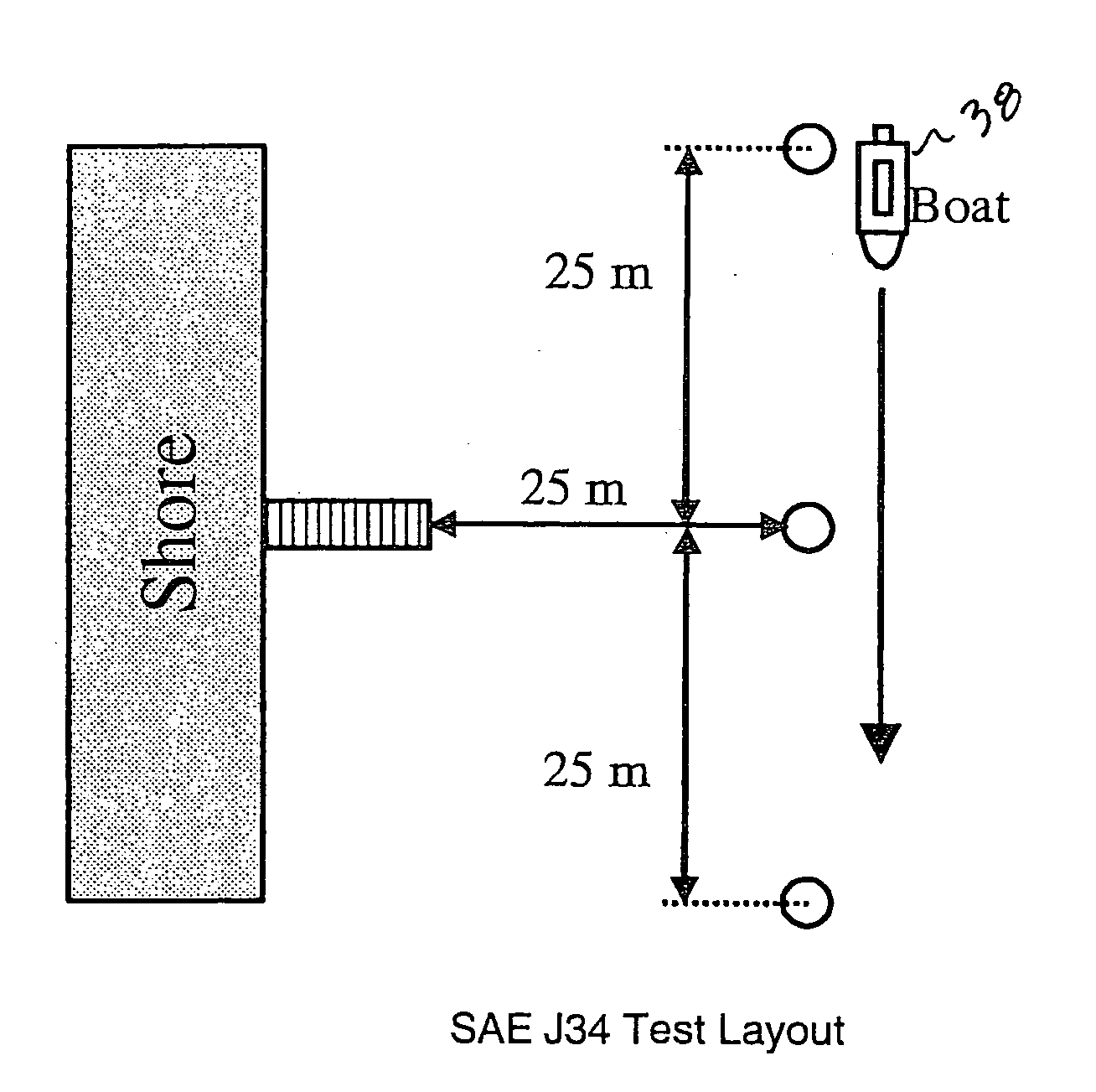
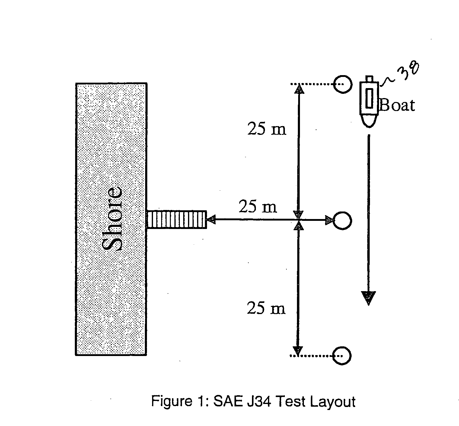
[0067] The noise detection apparatus 30 according to the teachings of the present invention shown in FIG. 9. The system utilizes a range finder 32, a microphone 34, and a controller 36. Controller 36 utilizes output signals from range finder 32 in the form of range values in combination with received sounds detected by microphone 34 from a noise producing target 38 to calculate the amount of noise being produced at the target. It is envisioned noise producing target 38 can be a movable vehicle such as a boat or automobile. Range finder 32 is configured to transmit and receive a reflected signal using known propagation principles to calculate the distance to the target. It is envisioned range finder 32 can use a pulse laser, radar, or ultrasound. Microphone 34 is preferably a shotgun microphone having known properties ...


PUM


Abstract

An accurate measure of normally operating noise is required for a useful noise measurement system. A device is needed to make a representative measure of the boat's acoustic power using measured boat sound level with integrated corrections for sensed distance to the boat and measured ambient sound level. This device needs to make this measurement process invisible, automatic, and accurate from a law enforcement point of view.

Description

CROSS-REFERENCE TO RELATED APPLICATIONS [0001] This claims the benefit of U.S. Provisional Application No. 60 / 577,939, filed on Jun. 7, 2004 The disclosure of the above application is incorporated herein by referenceFIELD OF THE INVENTION [0002] The present invention relates to noise measurement equipment and, more particularly, to equipment configured to repeatably measure noise from a moving object at variable distance. BACKGROUND & SUMMARY OF THE INVENTION [0003] Excessive noise levels on lakes are the source of many community problems. Given the increasing numbers of boats on lakes, shoreline residents who wish to maintain a peaceful environment have a vested interest in controlling noise pollution. [0004] Current standards for measuring noise levels of boats are written in various State Acts. The current standards often cited are testing procedures SAE J2005 (SAE 1991b) and SAE J1970 (SAE 1991a), which tend to discourage the state law officials who try to apply and enforce them...

Claims


Application Information

Patent Timeline
IPC IPC(8): E02B3/00
CPCG01N2291/02872G01H3/10
Inventor RADCLIFFE, CLARK J.
Owner BOARD OF TRUSTEES OPERATING MICHIGAN STATE UNIV
Why Eureka
Eureka Blog
Learn More