Fuel system for premix burner of a direct-fired steam generator

a fuel system and direct-fired technology, which is applied in the direction of water feed control, combustion control, lighting and heating apparatus, etc., can solve the problems of increasing the overall reliability and adding a lot of expens

Inactive Publication Date: 2006-01-05
DEERE & CO
View PDF5 Cites 8 Cited by
  • Summary
  • Abstract
  • Description
  • Claims
  • Application Information

AI Technical Summary

Benefits of technology

[0009] In a supercharged or turbocharged engine system, the air entering the carburetor is at an elevated pressure. A pressure-balance air line is connected from the downstream side of the carburetor to the diaphragm. This equalizes the pressure on the diaphragm and allows its movements to be controlled by the pressure drop through the carburetor. Instead of creating a low-pressure downstream of the carburetor, one can create a high pressure upstream of the carburetor. By using a blower or other air-pumping device to force air through the carburetor, one can induce the proper fuel flow into the air stream.

Problems solved by technology

Systems of this type having fuel metered in the known ways have one or more of the following drawbacks: (1) the burner's output is changed in a step progression, with each step depending on the size and quantity of valves opened to regulate the fuel / air mixture; (2) fuel flow is often not related to the airflow through the burner; (3) to have a variety of firing rates, either a fuel flow control system including several fuel valves is needed, or a complicated variable valve system is needed, with either system adding great expense while decreasing overall reliability; and requiring a high amount of piping which makes them undesirable for mobile application.

Method used


Image

  • Fuel system for premix burner of a direct-fired steam generator
  • Fuel system for premix burner of a direct-fired steam generator
  • Fuel system for premix burner of a direct-fired steam generator

Examples


Embodiment Construction

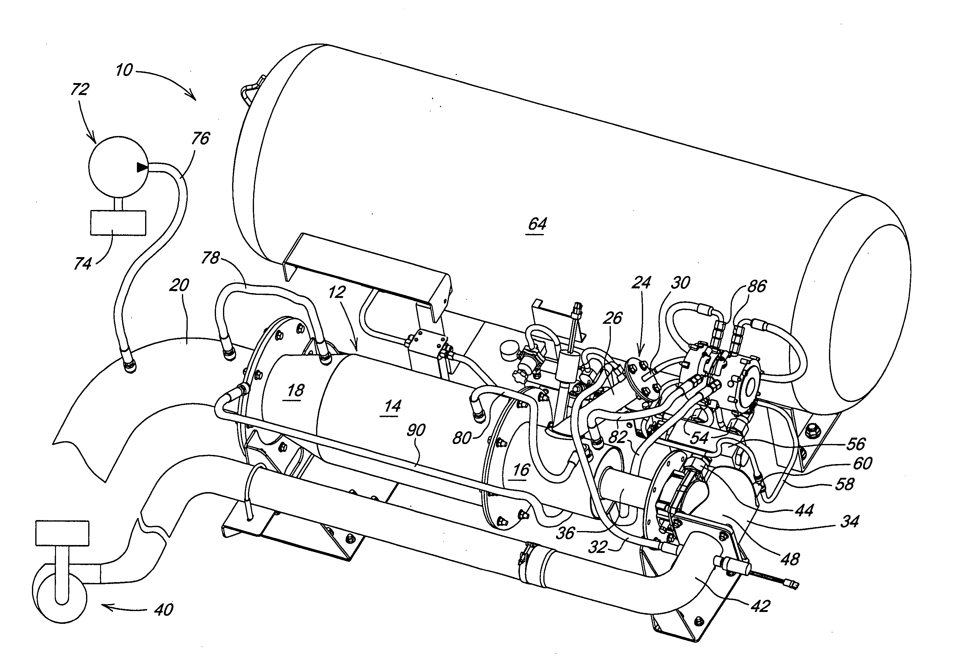
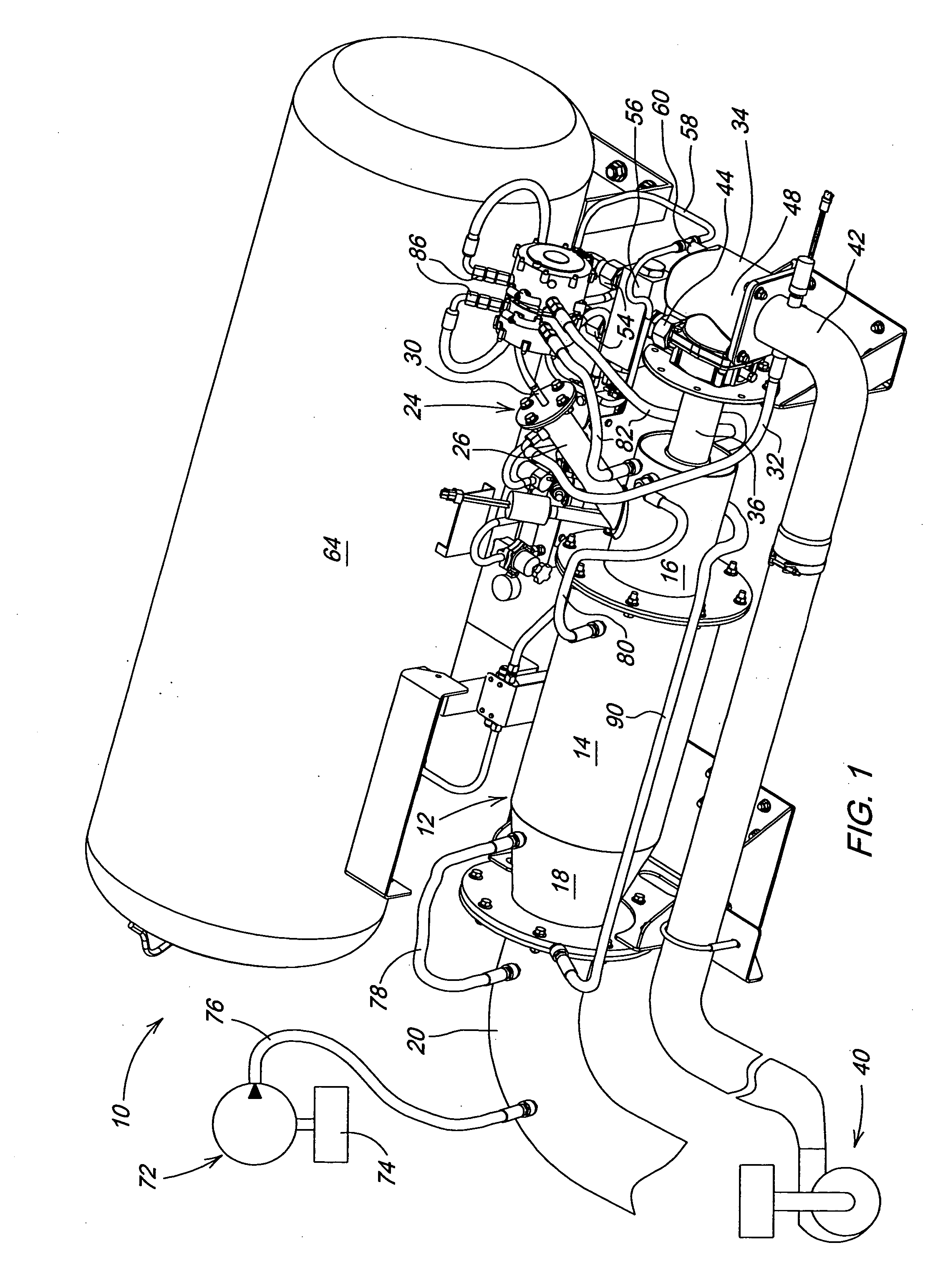
[0015] Referring now to FIGS. 1-3, there is shown a steam generator assembly 10 including a steam generator body 12 having a cylindrical inlet section 14 to which a cylindrical burner-head 16 is coupled, and having a conical outlet section 18 to which one end of an elbow 20 is coupled, the other end of the elbow 20 being coupled to a static mixer 22 (FIG. 3). A pilot burner arrangement 24 includes a tube 26 mounted so as to project through and terminate at an interior surface of a lower region of the burner-head 16. An igniter 28, which may be a spark plug or other type of sparking device, is mounted to the tube 26 so as to selectively create a spark at an interior location of the tube 26 for igniting a fuel / air mixture resulting when vaporized fuel enters by way of a pilot fuel inlet 30 provided in a cover at an inlet end of the tube 26 and when air enters by way of an pilot burner air line 32 coupled to an upper location of the tube 26.

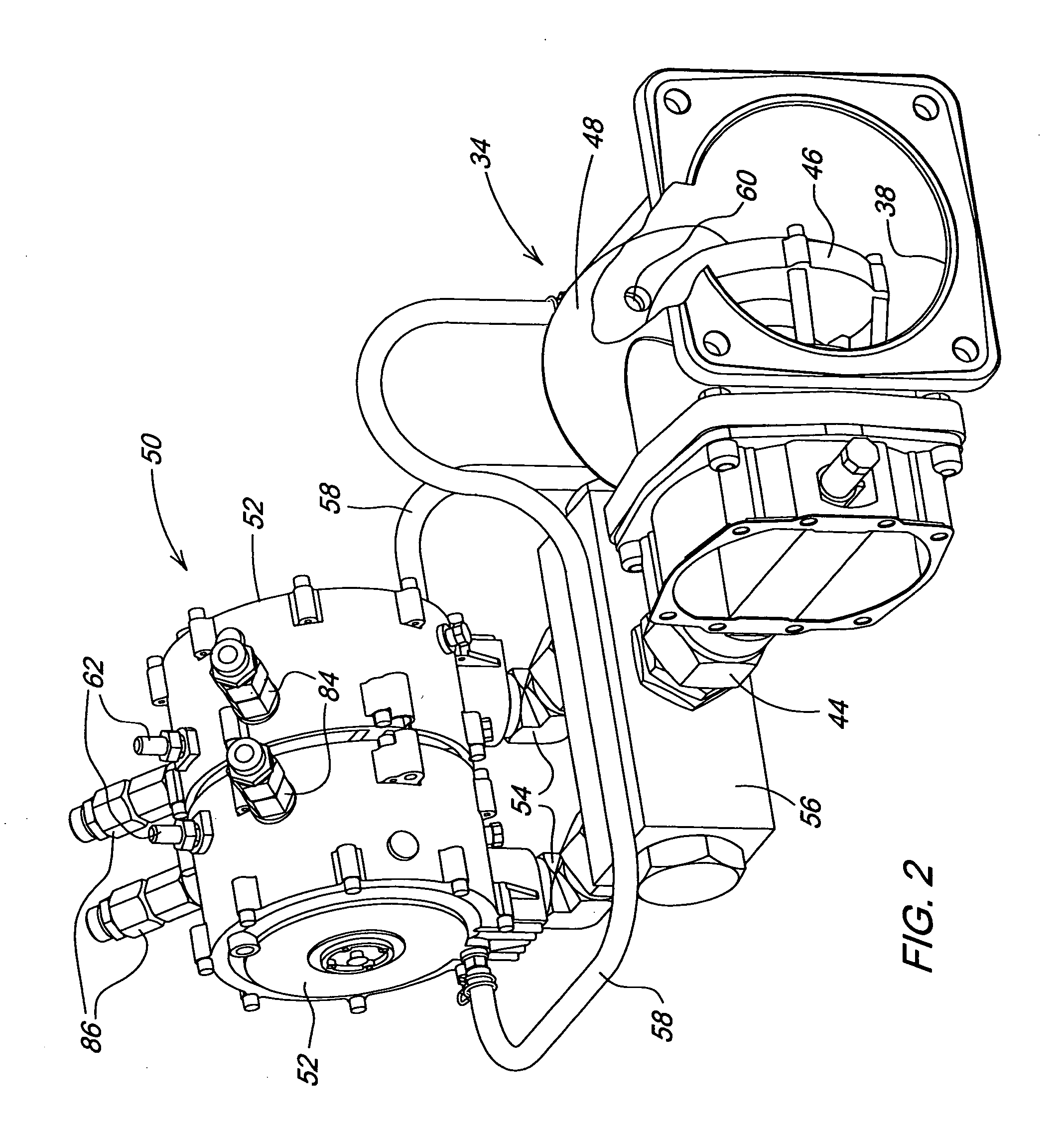
[0016] A carburetor 34 has an outlet coupled...


PUM


Abstract

A direct-fired, propane powered steam generator is provided with a carburetor, which receives vaporized propane from a converter arrangement which converts liquid propane to vapor, receives pressurized air and feeds a mixture of vaporized propane and air into the combustion chamber of the steam generator. The amount of air delivered to the carburetor is variable, with the amount of vaporized propane entering the carburetor being determined by the position of a metering valve which varies in accordance with the amount of air passing through the carburetor. The converter arrangement receives liquid propane and is coupled to process water heated in the water jackets of the combustion chamber and adjacent structure, the converter arrangement being designed so that heat from the water is transferred for effecting vaporization of the liquid propane. The flow of liquid propane for combustion in a pilot burner and for combustion in the main combustion chamber may be controlled using various arrangements of solenoid-operated lock off valves and/or vacuum-operated fuel lock off filters and/or air pressure balance control valves.

Description

FIELD OF THE INVENTION [0001] The present invention relates to direct-fired steam generators, and, more specifically, relates to systems for supplying a combustible mixture of fuel and air to the premix burners of such generators. BACKGROUND OF THE INVENTION [0002] Applications in which a forced airflow is used with a premix burner require a high-pressure fuel delivery system in order to overcome the high air pressures (generally from 2˜15 psi) in the burner. In the present systems, fuel is metered in a binary fashion using several solenoid valves (see U.S. Pat. Nos. 6,135,063 and 4,462,342, for example) or with electronic controls utilizing several sensors and valves (see U.S. Pat. No. 5,685,707, for example). [0003] A typical known premix burner layout includes main fuel and air passages which merge at a burner inlet and are fed into the burner combustion chamber where the mixed fuel and air are ignited. Water for producing steam is introduced into an inlet at one end of the chamb...

Claims


Application Information

Patent Timeline
Patent Type & Authority Applications(United States)
IPC IPC(8): F02M1/00
CPCF22B1/22F23N2037/14F23N2035/16F23N1/002F23N2235/16F23N2237/14
Inventor SCHLESSER, WALTER MARKKRAUS, TIMOTHY JAMESHARDEN, PHILIP ALAN
Owner DEERE & CO
Why Eureka
Try Eureka