Megasonic cleaning efficiency using auto-tuning of a RF generator at constant maximum efficiency

a technology of rf generator and rf generator, which is applied in the direction of mechanical vibration separation, cleaning using liquids, chemistry apparatus and processes, etc., can solve the problems of difficult consistency and substrate-to-substrat control, excessive volume of cleaning chemicals, and long processing time of batch substrate cleaning process, so as to reduce the number of substrate damage, reduce the number of cleaning processing time, and increase the power acoustic energy

Inactive Publication Date: 2006-01-05
LAM RES CORP
View PDF3 Cites 6 Cited by
  • Summary
  • Abstract
  • Description
  • Claims
  • Application Information

AI Technical Summary

Benefits of technology

[0034] The present invention provides the advantage of significantly reduced cleaning processing time because the higher power acoustic energy can be used without damaging the substrate being cleaned.
[0035] The present invention also reduces the number of substrates damaged due to excess acoustic energy being applied to the substrate.
[0036] The auto-tuned RF generator also automatically adjusts for process-induced impedance changes such as different cleaning chemistries, different locations of the substrate, different process tank configurations etc, thereby providing a more flexible and robust cleaning process.

Problems solved by technology

A batch substrate cleaning process typically requires lengthy processing times, and also can consume excessive volumes of cleaning chemicals 16.
Additionally, consistency and substrate-to-substrate control are difficult to achieve.
The occurrence of hot spots, primarily the result of constructive interference due to the use of multiple transducers and to reflection, can also increase with additional multiple-substrate surface areas.
These issues problems are typically addressed by depending on the averaging effects of the multiple reflections of the acoustic energy on the substrate, which can lead to a lower average power to the substrate surfaces.
The constructive interference can cause excess energy that can cause hot spots on the surfaces of the substrates 14 being cleaned.
However, the reduced power of the RF signal 35 and the emitted energy 15 increases the cleaning process time required to achieve the desired cleaning result.

Method used


Image

  • Megasonic cleaning efficiency using auto-tuning of a RF generator at constant maximum efficiency
  • Megasonic cleaning efficiency using auto-tuning of a RF generator at constant maximum efficiency
  • Megasonic cleaning efficiency using auto-tuning of a RF generator at constant maximum efficiency

Examples


Embodiment Construction

[0057] Several exemplary embodiments for an acoustic energy cleaning system that automatically adjusts RF signal applied to the transducer for maximum efficiency will now be described. It will be apparent to those skilled in the art that the present invention may be practiced without some or all of the specific details set forth herein.

[0058] As described above, it is very important to increase the cleaning effectiveness, efficiencies and throughput rate of substrate cleaning systems, while reducing probability of damage to the substrate. These requirements are exacerbated by the continuously shrinking device sizes and the fact that many cleaning systems are evolving to single substrate cleaning systems.

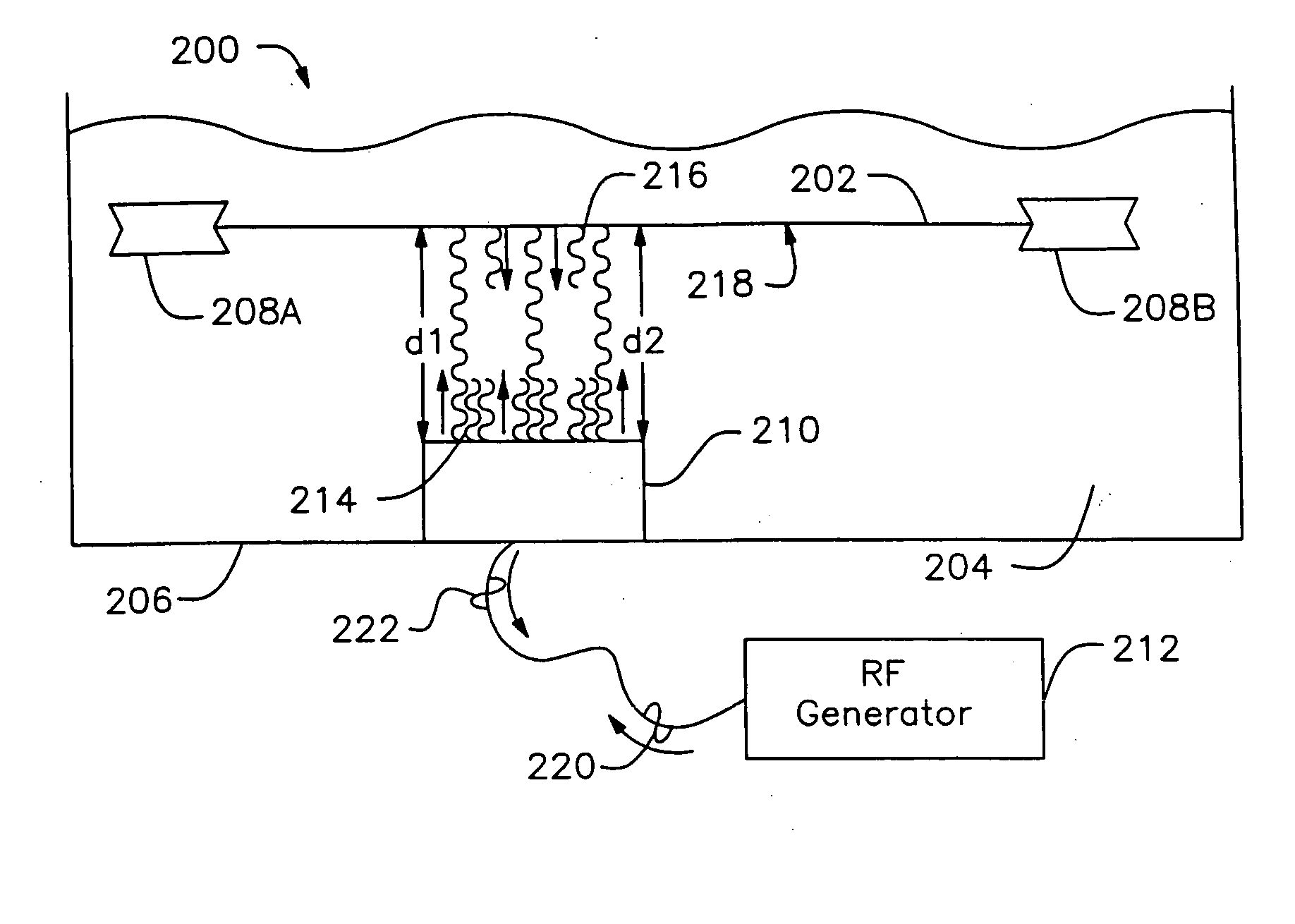
[0059]FIGS. 2A and 2B show a dynamic, single substrate cleaning system 200, in accordance with one embodiment of the present invention. FIG. 2A shows a side view of the dynamic, single substrate cleaning system 200. FIG. 2B shows a top view of the dynamic, single substrate cleaning...


PUM

PropertyMeasurementUnit
frequencyaaaaaaaaaa
frequencyaaaaaaaaaa
wavelengthaaaaaaaaaa

Abstract

A system and method of cleaning a substrate includes a megasonic chamber that includes a transducer and a substrate. The transducer is being oriented toward the substrate. A variable distance d separates the transducer and the substrate. The system also includes a dynamically adjustable RF generator that has an output coupled to the transducer.

Description

CROSS REFERENCE TO RELATED APPLICATIONS [0001] This application is a divisional of claims priority from U.S. patent application Ser. No. 10 / 360,322 filed on Feb. 6, 2003 and entitled “Improved Megasonic Cleaning Efficiency Using Auto-Tuning of an RF Generator at Constant Maximum Efficiency,” which is incorporated herein by reference in its entirety.BACKGROUND OF THE INVENTION [0002] 1. Field of the Invention [0003] The present invention relates generally to systems and methods of tuning an RF generator, and more particularly, to methods and systems for automatically tuning an RF generator for a substrate cleaning system. [0004] 2. Description of the Related Art [0005] The use of acoustic energy is a highly advanced, non-contact, cleaning technology for removing small-particles from substrates such as semiconductor wafers in various states of fabrication, flat panel displays, micro-electro-mechanical systems (MEMS), micro-opto-electro-mechanical systems (MOEMS), and the like. The cle...

Claims


Application Information

Patent Timeline
Patent Type & Authority Applications(United States)
IPC IPC(8): B08B3/12B06B1/02B08B3/10H01L21/00
CPCB06B1/0253B06B2201/71H01L21/67253B08B3/12H01L21/67057B08B3/10Y10S134/902
Inventor BOYD, JOHNKUTHI, ANDRASSMITH, MICHAEL G.R.ANDERSON, THOMAS W.THIE, WILLIAM
Owner LAM RES CORP
Why Eureka
Try Eureka