Infrastructure-independent deepwater oil field development concept

a deepwater oil field and infrastructure technology, applied in the direction of passenger handling equipment, lighting and heating equipment, borehole/well accessories, etc., can solve the problems of not being able to operate tankers during the day, the use of seabed pipeline systems for transporting hydrocarbons to shore may not be economically feasible, and the construction of pipelines to shore is typically not practicabl

Inactive Publication Date: 2006-01-05
CONOCOPHILLIPS CO
View PDF12 Cites 62 Cited by
  • Summary
  • Abstract
  • Description
  • Claims
  • Application Information

AI Technical Summary

Problems solved by technology

However, in some parts of the world, the use of a seabed pipeline system for transporting hydrocarbons to shore may not be economically feasible.
For offshore facilities located a great distance from shore, construction of a pipeline to shore is typically not practicable.
Thus, tankers are typically not operated during severe or unfavorable conditions.
As a result, long delay periods may occur between tanker availability for a particular site.
Because the surface area and weight carrying capacity of the production platform 2 is extremely limited, storage facilities provided on a platform 2 are limited in size and, thus, inadequate for handling large quantities of hydrocarbons which may be produced during periods of shuttle tanker or other hydrocarbon transport unavailability.
Like other tanker-based storage systems described above, production operations which use DSL systems 30 are susceptible to interruptions in production due to severe weather conditions and periods of shuttle tanker unavailability.
As a result, these systems are expensive and limited in capacity.
Other offshore storage systems exist for use in shallow water applications; however, for the most part, these systems are not applicable for use in deepwater applications.

Method used


Image

  • Infrastructure-independent deepwater oil field development concept
  • Infrastructure-independent deepwater oil field development concept
  • Infrastructure-independent deepwater oil field development concept

Examples


Embodiment Construction

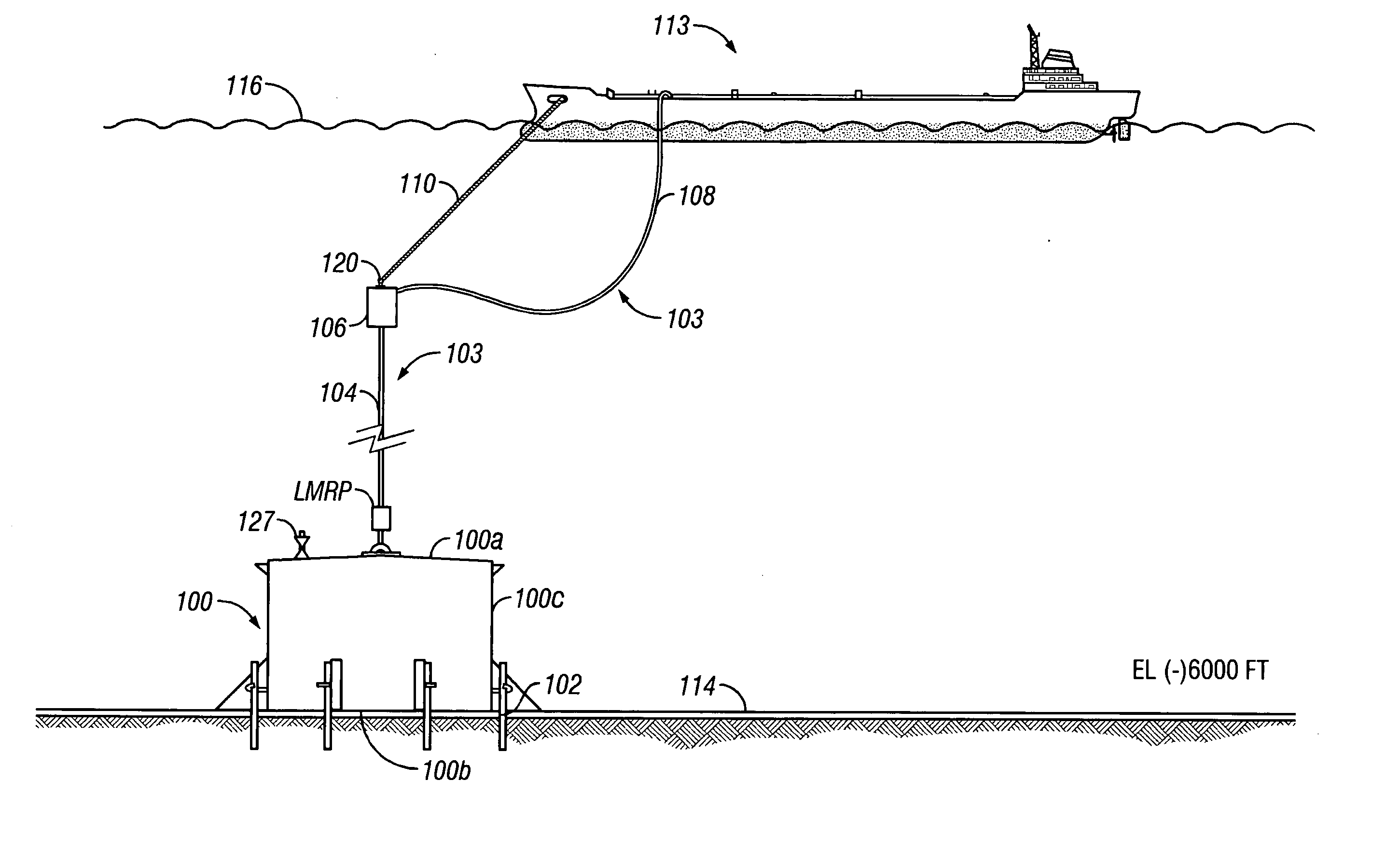
[0038] Referring to the drawings wherein like reference characters are used for like parts throughout the several views, FIG. 4 shows one embodiment of a seabed pertains subsea storage hydrocarbon storage and offtake system in accordance with the present invention. The storage and offtake system comprises a storage tank 100 adapted for placement on and, possibly, attachment to, the seabed 114. The tank 100 comprises a top 100a, a bottom 100b, and one or more side walls 100c. At the base of the tank 100, there is an amount of fixed ballast, such as sand, concrete or other dense material, to provide submerged weight to overcome the buoyancy force of the hydrocarbon when the tank 100 is filled to its maximum storage capacity. In the embodiment shown, the tank 100 rests on the sea floor at a depth of approximately 6000 feet.

[0039] The tank may comprise any configuration as determined by one skilled in the art, including cylindrical-shaped, box-shaped, or the like. Those skilled in the ...


PUM


Abstract

A method for developing a sub-sea hydrocarbons field includes sub-sea wells, sub-sea oil/gas separation, storing the degassed oil in a storage tank located or the seabed, liquefying natural gas aboard a vessel using liquid nitrogen aboard the vessel to obtain liquefied natural gas, transporting the liquefied natural gas to an onshore terminal, re-gasifying the liquefied natural gas, and obtaining a new batch of liquid nitrogen using energy recovered from the re-gasifying the liquefied natural gas.

Description

CROSS-REFERENCE TO RELATED APPLICATIONS [0001] This is a continuation-in-part of application Ser. No. 09 / 818,117 filed on Mar. 27, 2001, and assigned to the assignee of the present invention. That application is hereby incorporated by reference in its entirety.BACKGROUND OF INVENTION [0002] 1. Field of the Invention [0003] The invention relates generally to offshore oil and gas production and transportation. [0004] 2. Background Art [0005] A major factor in determining whether to exploit an offshore oil and gas field is the feasibility of handling and transporting the hydrocarbons to market once they are produced. Generally, hydrocarbons produced offshore must be transported to land-based facilities for subsequent processing and distribution. Temporary storage may be provided at the offshore production site for holding limited quantities of hydrocarbons produced and awaiting transport to shore. In some cases, equipment is also provided at the offshore production site for separating ...

Claims


Application Information

Patent Timeline
Patent Type & Authority Applications(United States)
IPC IPC(8): E21B29/12B63B27/24B63B27/34B63B35/44B65D88/78E21B43/01F25J1/02
CPCB63B27/24Y02T70/34B63B35/44B63B2035/448B65D88/78E21B43/01F25J1/0015F25J1/0022F25J1/0223F25J1/0234F25J1/0278F25J3/0406F25J3/04266F25J3/04521F25J3/04563F25J2210/42F25J2210/62F25J2260/44F25J2290/62B63B27/30Y02T70/00
Inventor CHOI, MICHAEL S.
Owner CONOCOPHILLIPS CO
Why Eureka
Try Eureka