
Power extractor circuit

a power extractor and circuit technology, applied in the direction of electric vehicles, electric generators, transportation and packaging, etc., can solve the problems of insufficient individual small-power packets, insufficient power generated by solar panels, inactive cell arrays, etc., and achieves low power, high current, and high voltage

Inactive Publication Date: 2006-01-05
MATAN STEFAN
View PDF10 Cites 372 Cited by
  • Summary
  • Abstract
  • Description
  • Claims
  • Application Information

AI Technical Summary

Benefits of technology

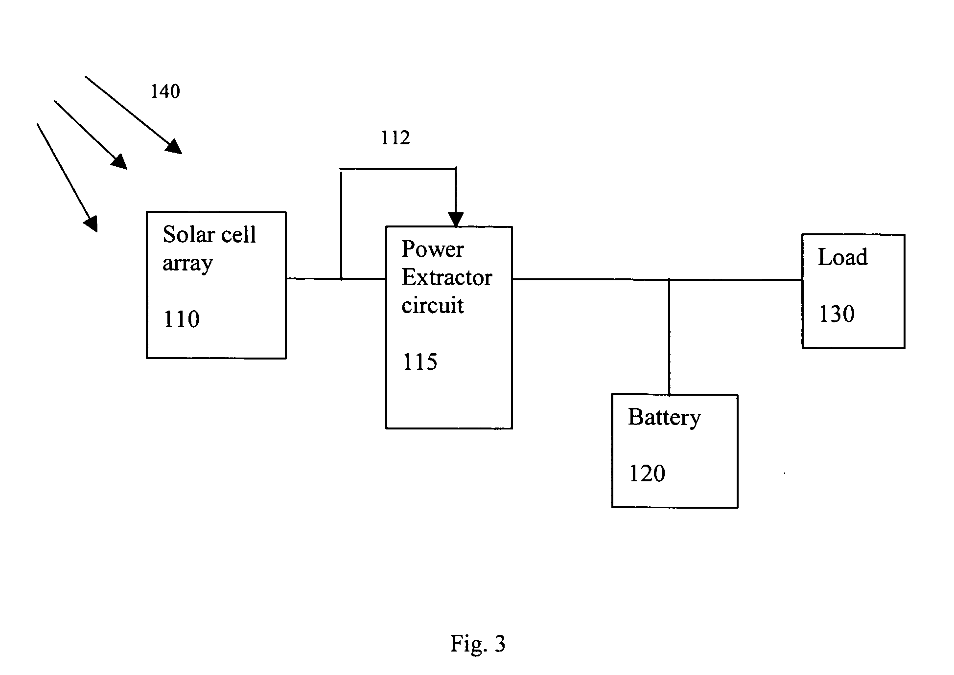
[0011] The power extractor circuit preferably comprises a voltage and current booster circuit. The voltage booster circuit is used to generate higher voltage and the current booster circuit to generate higher current. The power extractor circuit also is preferably designed to operate at all power levels of the solar cell array, providing the booster function at low power level during the low power period of the solar cell array, and preventing component failure at high power level during the normal operation of the solar cell array. The power extractor can further comprise a circuit breaker to prevent damage to the power extractor circuit at high power. Furthermore, many power extractor circuits can also be installed in series to cover a wide range of power level of the solar cell array.

Problems solved by technology

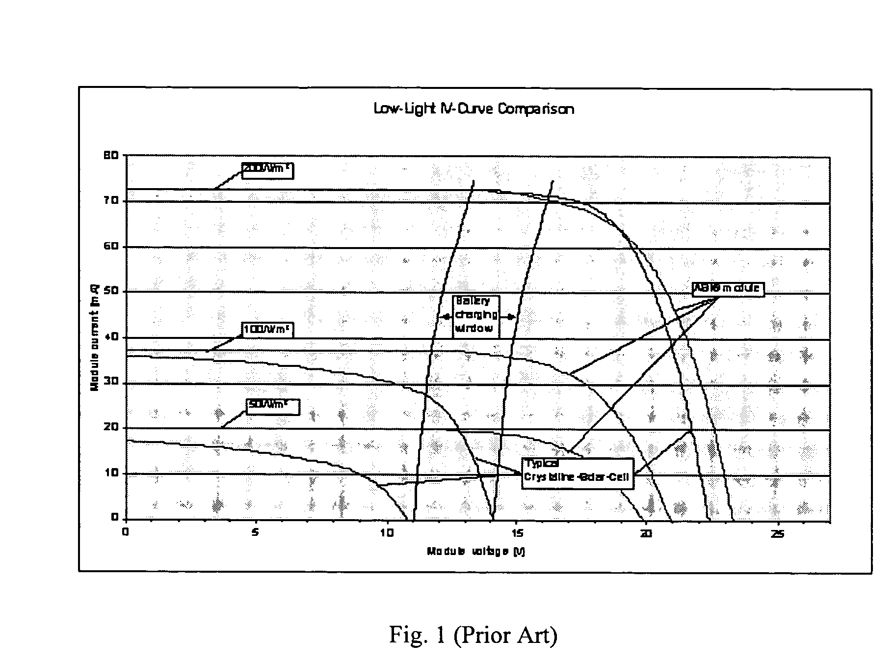
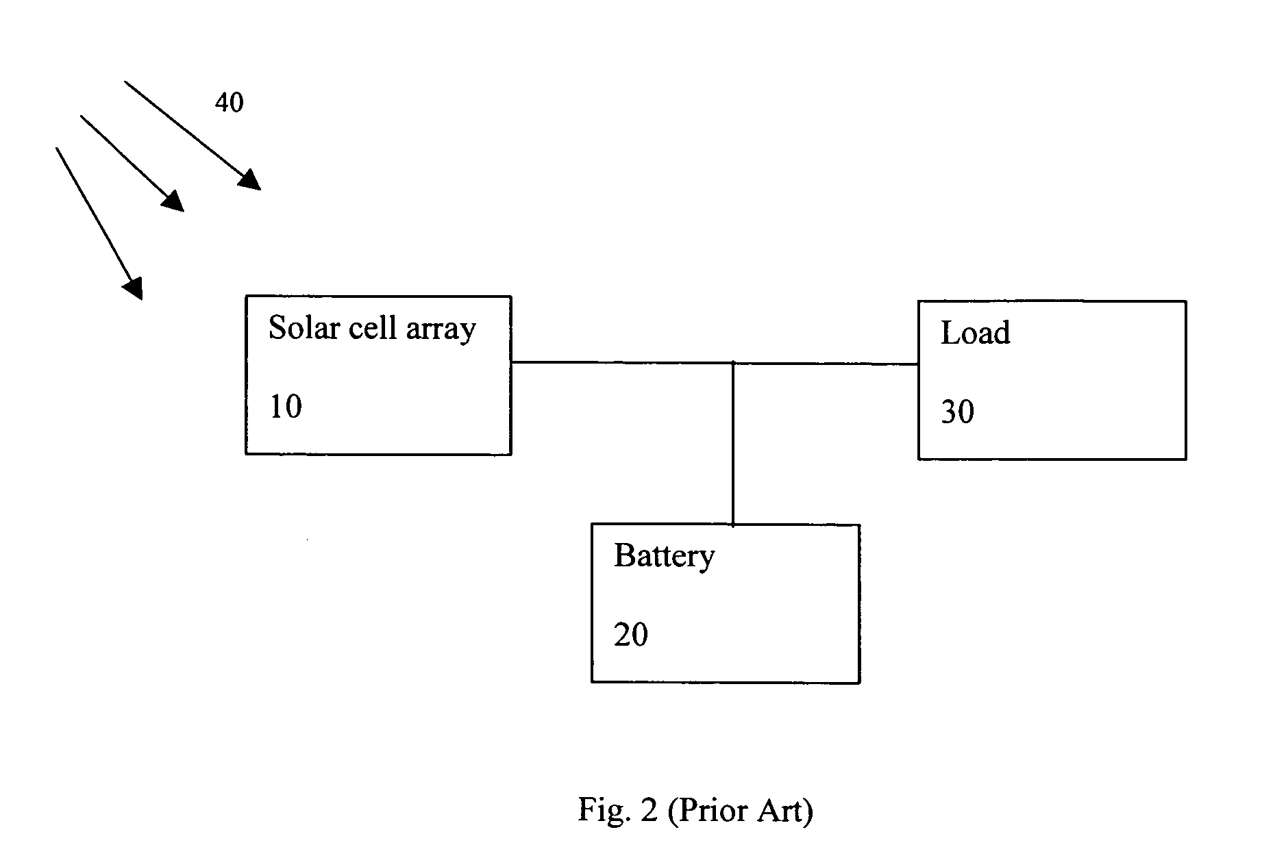
Under reduced incident solar radiation, the solar cell array does not receive enough sunlight to produce adequate power to charge the battery or to power a load, and therefore the solar cell array is inactive and the power generated by the solar panel is lost.
By itself, the individual small-power packet is not adequate for any useful work such as charging the battery or powering a load because of low voltage or low current or both.

Method used


Image

  • Power extractor circuit
  • Power extractor circuit
  • Power extractor circuit

Examples


Embodiment Construction

[0025] Solar cell arrays are excellent source of power since they can be operated anywhere under sunlight. However, improving the efficiency of the solar cell array is a major concern since solar cell array normally does not operated under low light conditions. Specifically, since almost all solar cell arrays come with a rechargeable battery, under the weather conditions that do not allow the solar cell array to produce adequate power to charge the battery, the solar cell array is inactive.

[0026] The present invention discloses a circuit to improve the efficiency of a solar cell array, and specifically to operate the solar cell array under low light conditions. The present invention is also suitable for low quality solar cells and flexible solar cells, because even in the best sunlight conditions, many of these solar cells could still produce less power, as much power as the high quality, single crystal silicon solar cells under low light conditions.

[0027] The basic component of t...


PUM


Abstract

The present invention discloses power extractor circuit used to capture the power of a solar cell array during its less-than-optimum conditions. Under reduced incident solar radiation, the low power level supplied by the solar cell array normally would not be adequate to operating a load, but with the presence of the power extractor circuit, the low power generated by the solar panel would be accumulated to a high enough level to overcome the energy barrier of the battery or the load. The power extractor circuit preferably comprises a voltage and current booster circuit, and is designed to operated at all power levels of the solar cell array: low power level to provide the booster function during the low power period of the solar cell array, and high power level to prevent component failure during the normal operation of the solar cell array. Many power extractor circuits can also be installed in series to cover a wide range of power level of the solar cell array. The present invention power extractor circuit can also be used in other power sources to utilize the portion of power which normally would have been lost.

Description

FIELD OF THE INVENTION [0001] This invention relates generally to a method and apparatus for harvesting power in the low power regimes from a power source and, more particularly, to a method and apparatus that delivers power output of a photovoltaic array during varying ambient weather conditions. BACKGROUND OF THE INVENTION [0002] Solar power is one of the clean and renewable sources of energy (the others being wind, geothermal steam, biomass, and hydroelectric) that have mass market appeal. Solar power uses energy from the sun to provide passive heating, lighting, hot water, and active production of electricity through photovoltaic solar cells. Photovoltaics are the most promising of active solar power which directly convert sunlight into electricity. However, photovoltaics are very expensive, in terms of high production cost and low efficiency. [0003] Significant works have been done to improve the efficiency of the photovoltaic array. One of the earliest improvements is the addi...

Claims


Application Information

Patent Timeline
IPC IPC(8): H02J7/00
CPCH02J7/35Y02E60/10H01M10/46Y10S323/906
Inventor MATAN, STEFAN
Owner MATAN STEFAN
Learn More