Coaxial electrical connector for hazardous locations

a technology of hazardous locations and electrical connectors, applied in the direction of coupling devices, coupling parts engagement/disengagement, coupling device connections, etc., can solve the problems of difficult or impossible to manually disconnect the connectors, difficult or impossible to uncouple the couplers, and commercial quick disconnect connectors are not readily usable, etc., to eliminate or reduce the possibility of accidental separation

Active Publication Date: 2006-01-05
WOODHEAD IND INC
View PDF4 Cites 24 Cited by
  • Summary
  • Abstract
  • Description
  • Claims
  • Application Information

AI Technical Summary

Benefits of technology

[0013] A mating female connector of the second embodiment includes a female connector insert carrying female connecting elements for mating with the male connecting elements, and a connector overmold covering the cord / insert interface. A second (or “female”) coupler having internal threads for engaging the male threads of the male coupler is rotatably mounted on the female connector insert. A second coupler overmold is fixed to the rear of the female coupler and extends about the outer periphery of the female coupler to form a second ratchet interface surface for progressive engagement and locking coupling with the first ratchet interface surface of the coupler overmold of the mating connector when the two connectors are connected.
[0014] The overmolds of the male and female couplers are made of plastic or other suitable yieldable material which permits progressive inter-engagement of the two ratchet interface surfaces as the connectors are assembled and tightened to provide a coupling force between the connectors which makes it very difficult or impossible to uncouple the couplers and disconnect the connectors manually. The coupling / uncoupling forces may be varied according to the hardness of the material chosen for the coupler overmolds or the angles of the adjacent ramps and axial latching surfaces of the ratchet interface surfaces to cover a range of coupling forces from merely resistant to manually difficult to those requiring a tool to de-couple.
[0015] When sufficient force is applied, whether manually or with pliers or other torquing hand tools, depending on the application and design, the materials of the coupler overmolds permit the axial locking surfaces of the engaged ratchet interface surfaces to deform, thus allowing the ratchet interface surfaces to ride over one another without permanent deformation to disconnect the connectors. Additionally, the opposing ratchet surfaces of the coupled male / female elements eliminate or reduce the possibility of accidental separation due to environmental vibration.

Problems solved by technology

Currently available commercial quick disconnect connectors are not readily usable in applications involving so-called hazardous locations.
In hazardous locations, it is specifically desired that “quick disconnect” electrical connections be incapable of manual disconnect because a spark may result, creating a hazard.
The overmolds of the male and female couplers are made of plastic or other suitable yieldable material which permits progressive inter-engagement of the two ratchet interface surfaces as the connectors are assembled and tightened to provide a coupling force between the connectors which makes it very difficult or impossible to uncouple the couplers and disconnect the connectors manually.

Method used


Image

  • Coaxial electrical connector for hazardous locations
  • Coaxial electrical connector for hazardous locations
  • Coaxial electrical connector for hazardous locations

Examples


Embodiment Construction

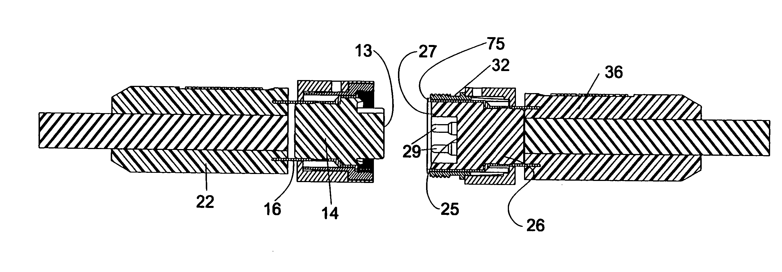
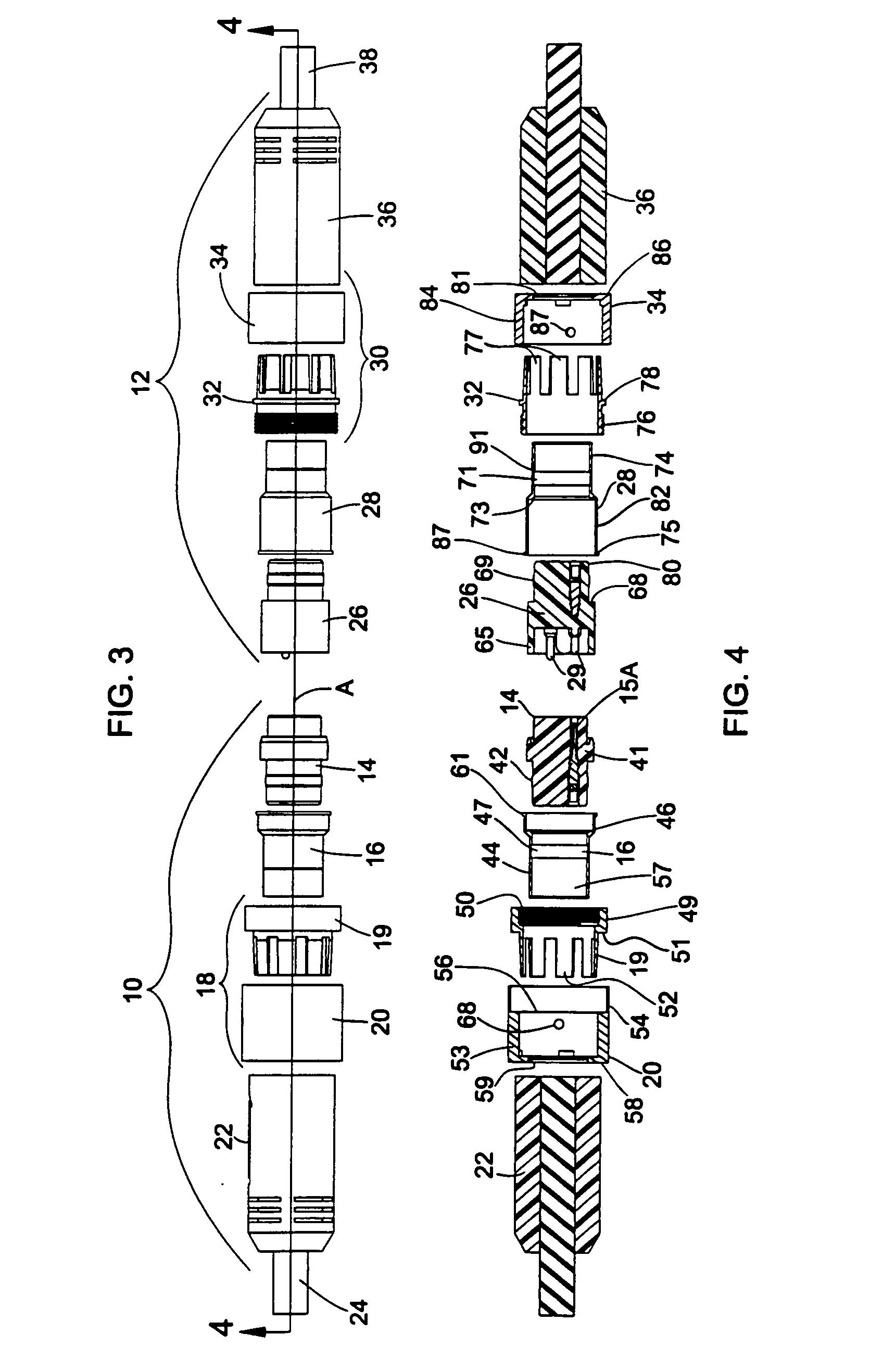
[0040] Referring first to FIG. 1, reference numeral 10 generally designates a female electrical connector adapted to be connected to a male quick-connect electrical connector generally designated 12. Before turning to the details of the components, reference is made to FIGS. 3 and 4 to identify the major components of the connectors 10, 12. Turning first to the female connector 10, it includes a female insert 14 of non-conducting material which is secured within an insert housing 16. As seen in FIG. 4, individual connecting elements 15A are embedded in the individual sockets 41 of insert 14. Surrounding the insert housing 16 is a ratchet assembly generally designated 18 and comprising a female coupler 19 and an outer housing generally designated 20. The distal end of the insert housing 16 extends to the rear (i.e. leftward in FIGS. 1 and 3) and is embedded in a connector overmold 22 which also encompasses the adjacent end of the cord or cable 24 to which the connector 10 is attached...


PUM


Abstract

Disclosed are two embodiments of a coaxial electrical connector designed for use in hazardous locations. Mating connectors are connected coaxially, and coupled together by means of a threaded connection. When the mating connectors are connected, they cannot be disconnected manually. Rather, a tool is necessary to disconnect the connectors. In one embodiment, each connector includes a generally cylindrical coupler member having integral, axial fingers or tines spaced circumferentially. The couplers are rotatably mounted to inserts in which the connecting elements are embedded. A ratchet assembly permits the couplers to be threaded together to make a connection but is overridden in the unconnecting direction, requiring a tool to be placed in the space between adjacent tines to connect the coupler to an associated outer housing which may then be turned to disconnect the connectors. In a second embodiment, coupling members are provided with a ratchet interface surface having interlocking, yieldable teeth so that when the coupling members are secured by hand, a retaining force secures the coupling members together and prevents disconnection by manual force alone, requiring tools to deform the teeth and disconnect the connectors.

Description

RELATED APPLICATIONS [0001] This application claims the benefit of co-pending, co-owned provisional application 60 / 571,107 for “Electrical Connector for Hazardous Locations”, filed May 14, 2004 and co-pending and co-owned provisional application 60 / 571,704 for “Electrical Connector for Hazardous Locations”, filed May 17, 2004.FIELD OF THE INVENTION [0002] The present invention relates to electrical connectors; and more particularly, it relates to coaxial electrical connectors which are designed to be connected manually (i.e. without tools), but which require tools such as a pliers or special wrench or device, to disconnect the mating male and female connectors. One application for connectors of this type is for use in so-called hazardous locations, such as petroleum processing and chemical manufacturing plants, where it is desired to avoid electrical arcing. BACKGROUND OF THE INVENTION [0003] Electrical connectors of the type referred to as “quick disconnect” connectors are in wides...

Claims


Application Information

Patent Timeline
Patent Type & Authority Applications(United States)
IPC IPC(8): H01R9/05
CPCH01R9/05H01R13/622H01R2103/00H01R24/40H01R13/6397
Inventor MURPHY, JOSEPH F.JANOWIAK, BRANDON
Owner WOODHEAD IND INC
Why Eureka
Try Eureka