Vapor compression refrigerator

a refrigerator and vapor compression technology, applied in the field of vapor compression refrigerators, can solve the problems of insufficient heat source for heaters, insufficient heating ability of heaters, insufficient heat supply of heat sources, etc., and achieve the effect of reducing the power of compressors and improving the engine warm-up performance of heat generating devices

Active Publication Date: 2006-01-12
DENSO CORP
View PDF7 Cites 39 Cited by
  • Summary
  • Abstract
  • Description
  • Claims
  • Application Information

AI Technical Summary

Benefits of technology

[0017] A second object of the invention is to provide an automotive climate control system in which an auxiliary heating function works in winter or cold areas while at the same time preventing the frosting of the window glass.
[0038] According to another aspect of the invention, there is provided an automotive climate control system comprising a closed refrigerant circuit for conducting the normal refrigeration cycle and a closed cooling water circuit for performing the heating operation using the engine cooling water, wherein the closed refrigerant circuit includes a bypass leading to a path connecting a low-pressure-side heat absorber and an accumulator from the inlet of a switching means circumventing a high-pressure-side heat emitter and a water-refrigerant heat exchanger arranged upstream of the main heater in the cooling water flow between the engine and the main heater for exchanging heat between the refrigerant discharged from a compressor and the cooling water discharged from the engine, wherein the refrigerant is supplied only to the water-refrigerant heat exchanger using the bypass while no refrigerant is supplied to the low-pressure-side heat absorber during the heating (hot gas) operation. As a result, the auxiliary heating function is exhibited to promote the temperature increase of the engine cooling water when the atmospheric temperature and thus shorten the time before the passenger compartment reaches a comfortable temperature. At the same time, the condensed water of the low-pressure-side heat absorber is evaporated and the window glass is prevented from being fogged.

Problems solved by technology

Especially in winter, a sufficient amount of heat cannot be supplied as a heat source for the heater.
In the hybrid car, therefore, the engine is required to run to secure the heat source for the heater even while the vehicle is driven at low speed at the sacrifice of a low fuel consumption efficiency.
In ordinary vehicles, on the other hand, the recently improved engine efficiency has reduced the waste heat generated by cooling the engine, thereby posing a problem, as in the hybrid car, that the heat source for the heater is insufficient.
This poses the problem that the heating ability of the heater cannot be sufficiently exhibited.
In the case where the heating operation is started while the cooling water temperature is still low at the time of starting the engine, however, air not sufficiently heated would be blown into the passenger compartment and the occupants would feel uncomfortable.
The system using the heat pump cycle, therefore, cannot be used in an environment such as cold areas in the winter season.
The condensed water, the frost, etc. generated in the inner heat exchanger 6 during the cooling operation is heated and evaporated during the heating operation, and the resultant vapor is liable to be blown against and fog the window glass.

Method used


Image

  • Vapor compression refrigerator
  • Vapor compression refrigerator
  • Vapor compression refrigerator

Examples


first embodiment

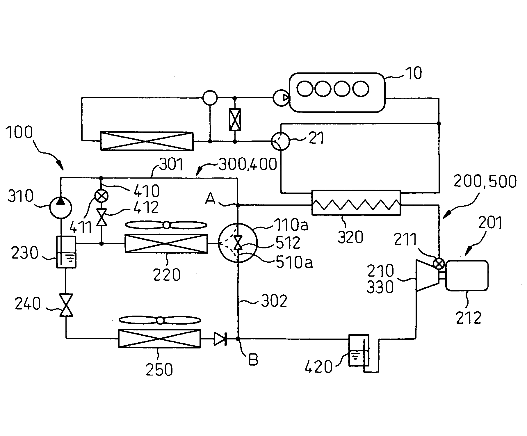
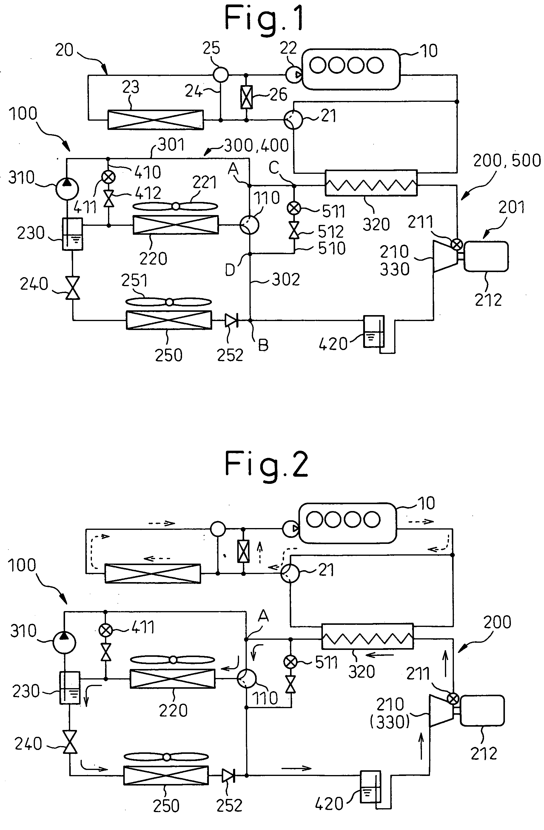
[0056] This embodiment represents an application of a vapor compression refrigerator 100 according to the invention to a climate control system of a hybrid car having a water-cooled engine (heat engine or internal combustion engine) 10 as a drive power source and a drive motor. FIG. 1 is a schematic diagram showing the vapor compression refrigerator 100 according to the first embodiment. According to this invention, the engine 10 corresponds to a heat generating device producing waste heat for temperature control.

[0057] The vapor compression refrigerator 100, as shown in FIG. 1, has built therein a Rankine cycle 300, a heat pump cycle 400 and a hot gas cycle 500 based on the well-known refrigeration cycle 200. The cycles 200, 300, 400 and 500 are explained in that order below.

[0058] First, in the refrigeration cycle 200, cold and heat are used for the air-conditioning operation by moving the heat on low-temperature side to high-temperature side. The refrigeration cycle 200 is conf...

second embodiment

[0109] A second embodiment of the invention is shown in FIG. 7. In the second embodiment, the condenser 220 of the first embodiment is changed. Specifically, the condenser 220 assumes the form of a subcool condenser having what is called a gas-liquid separator with a gas-liquid separator 230 and a liquid refrigerant super-cooler 231 arranged in that order on the outlet side of the refrigerant during the operation of the Rankine cycle. The condenser 220, the gas-liquid separator 230 and the liquid refrigerant super-cooler 231 may be combined into a gas-liquid separator-integrated subcool condenser.

[0110] As a result, during the operation of the Rankine cycle 300, the liquid-phase refrigerant flowing out from the condenser 220 and separated by the gas-liquid separator 230 is further cooled by the liquid refrigerant super-cooler 231 and supplied to the liquid pump 310. Even in the case where the pressure is reduced (negative pressure) while the liquid pump 310 sucks in the refrigerant...

third embodiment

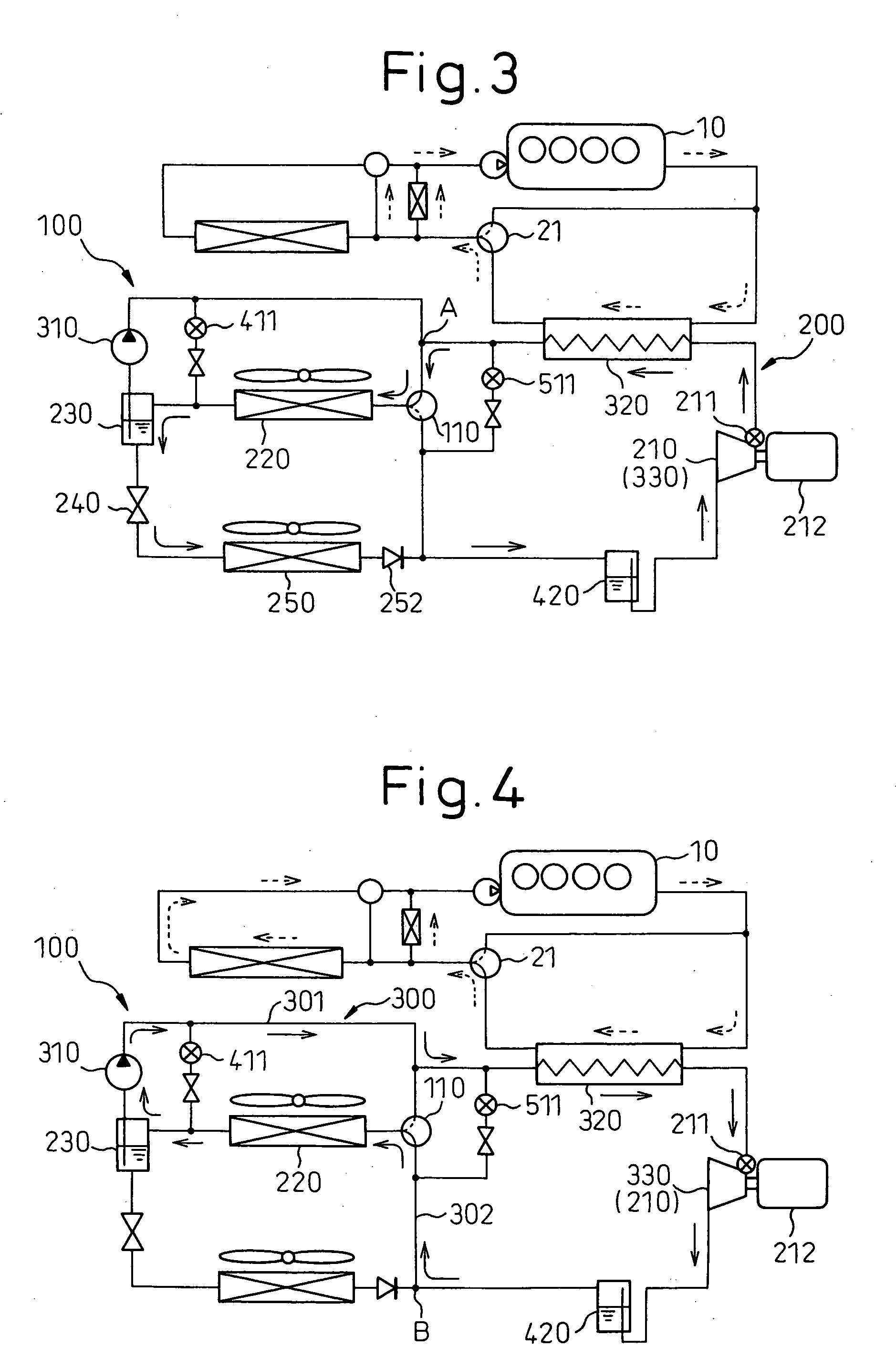
[0113] A third embodiment of the invention is shown in FIG. 8. In the third embodiment, the accumulator 420 is set at a position different from the first embodiment.

[0114] In this case, the accumulator 420 is arranged outside the refrigerant path during the operation of the refrigeration cycle 200 (while the evaporator 250 exhibits the refrigeration function). Specifically, the accumulator 420 is interposed between the cycle switch valve 110 and point B (second bypass 302).

[0115] As a result, the refrigerant is prevented from flowing through the accumulator 420 during the operation of the refrigeration cycle 200, thereby reducing the pressure loss during the refrigerant flow for an improved refrigeration ability.


PUM


Abstract

A vapor compression refrigerator having a refrigeration cycle (200) is disclosed. In a Rankine cycle (300), a refrigerant is circulated through a pump (310), a heater (320), an expander (330) and a condenser (220) in that order, and power is recovered by the expander 330 due to the expansion of the refrigerant from the heater (320). In a host gas cycle (500), on the other hand, the inlet of the compressor (210) can be connected from a point between the pump (310) and the heater (320) by a switching path (510) having a first restricting portion (510), the refrigerant is circulated by the compressor (210) through the heater (320) and the switching path (510) in that order, and the heater (320) exhibits the function of heating a heat generating device (10).

Description

BACKGROUND OF THE INVENTION [0001] 1. Field of the Invention [0002] The present invention relates to a vapor compression refrigerator having a Rankine cycle, for recovering power, utilizing the waste heat of a heat generating device and a hot-gas cycle capable of heating the heat generating device, effectively applicable to an automotive climate control system mounted on a vehicle and having an auxiliary heating function adapted to help increase the engine water temperature to secure a comfortable temperature of the passenger compartment within a short period of time, from the time of starting the heating operation, when the engine water temperature is low. [0003] 2. Description of the Related Art [0004] In a conventional vapor compression refrigerator disclosed in Japanese Patent Publication No. 2540738, for example, a component part (condenser) of a refrigeration cycle is shared to form a Rankine cycle, the waste heat of the vehicle engine (heat generating device) is recovered as ...

Claims


Application Information

Patent Timeline
Patent Type & Authority Applications(United States)
IPC IPC(8): F25D21/06F25B27/00B60H1/32
CPCB60H1/00878B60H1/32B60H1/3204F25B2327/001B60H2001/3295B60H2001/3297F25B27/00B60H2001/00928
Inventor TAKANO, YOSHIAKIINABA, ATSUSHIBAN, KOICHITAKAHASHI, KOJI
Owner DENSO CORP
Why Eureka
Try Eureka