Ship with wave energy engulfing propulsors

a propulsor and wave energy technology, applied in the field of ships with wave energy engulfing propulsors, can solve the problems of bulbous bows actually increasing drag, affecting the performance of ships, and increasing the power requirements of all practical purposes, so as to reduce the amplitude and hence the resistance of the ship's bow wave, improve the hydrodynamic force, and reduce the friction of the wetted area

Inactive Publication Date: 2006-01-12
BURG PAULETTE RENEE
View PDF2 Cites 5 Cited by
  • Summary
  • Abstract
  • Description
  • Claims
  • Application Information

AI Technical Summary

Benefits of technology

[0006] The instant invention combines bow oriented water propulsor(s) with variations of a secondary bow disposed proximal a lower portion of the ship's main bow. By having a water inlet for the bow oriented water propulsor(s) disposed properly in relation to the secondary bow it is possible to provide an enhanced hydrodynamic force that subtracts from the energy in the ship's bow wave. The effect is to reduce the amplitude and hence the resistance of the ship's bow wave. A related feature is to have a pressurized air or gas layer in a recess in the underside of the hull. This gas layer not only reduces wetted area friction of the ship but also allows the water discharge from the bow oriented water propulsor(s) to be discharged into gas rather than water. The effect of discharging the bow oriented water propulsor(s) into gas rather than water is an increase in the efficiency of the bow oriented water propulsor(s). A further advantage is that a steering and / or reversing systern(s) may be applied to the bow oriented water propulsor(s). The steering and / or reversing systern(s) would be internal to the pressurized gas recess when moving forward so they do not add to resistance. The advantage of having steering and / or reversing capabilities in the bow makes for a much more maneuverable ship at all speeds.

Problems solved by technology

As speed is increased beyond those values, powering requirements become excessive for all practical purposes.
However, though some small improvements have been made, speeds still remain embarrassingly slow for displacement hulls.
It is of interest that bulbous bows can actually increase drag at low speeds since they increase wetted area friction.
However, the air layers, while still effective in reducing frictional resistance, are not noted to provide as high a percentage of efficiency improvement at higher speeds where the wave resistance predominates.

Method used


Image

  • Ship with wave energy engulfing propulsors
  • Ship with wave energy engulfing propulsors
  • Ship with wave energy engulfing propulsors

Examples


Embodiment Construction

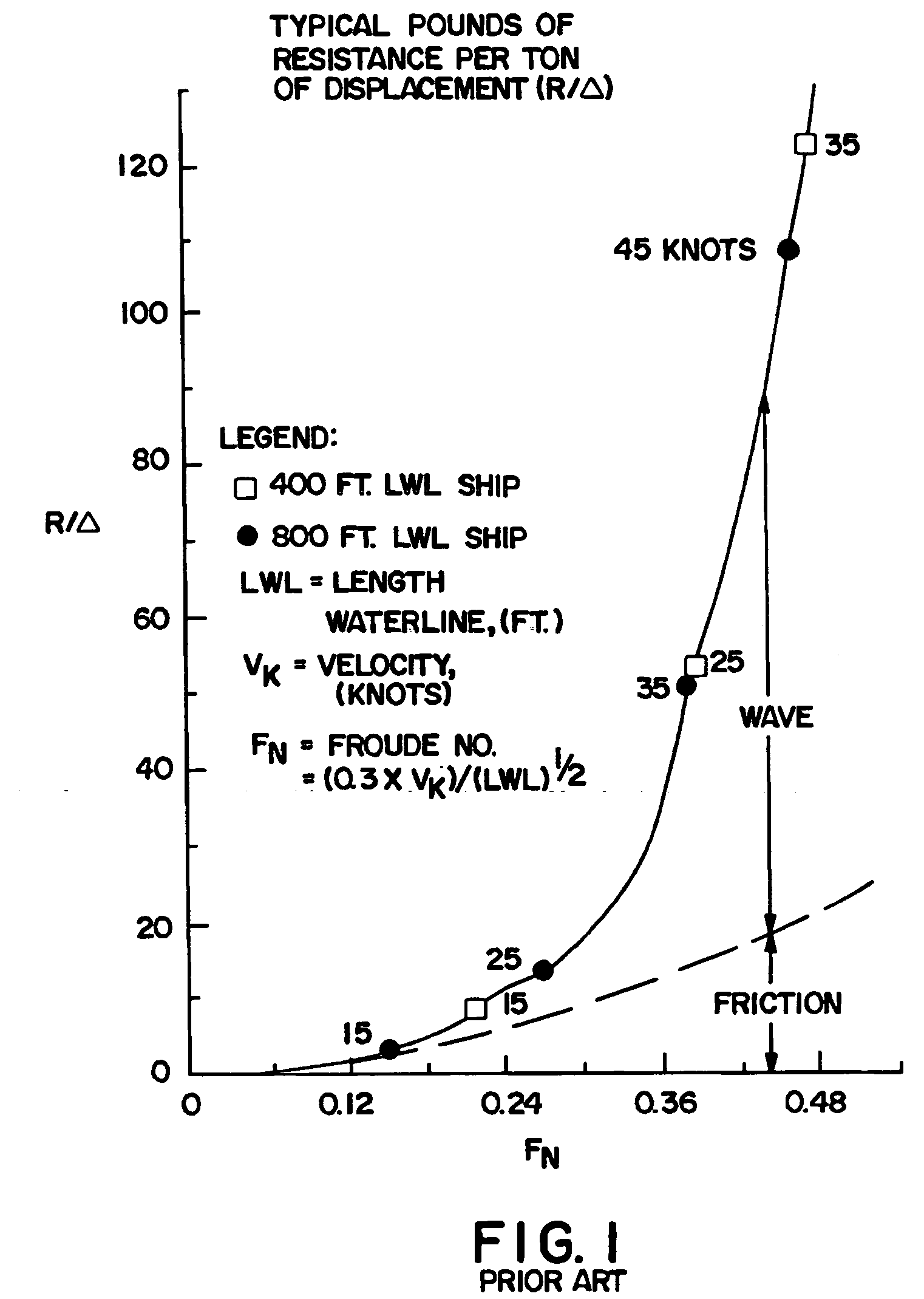
[0057]FIG. 1 present a graph that shows the effects of the two primary resistance factors for prior art displacement hull ships. These primary resistance factors are friction and wave resistance. The graph presents them as Resistance per Ton of Displacement (R / Δ) vs. Froude Number (Fn) for some typical displacement ships. By standard Naval Architecture terminology, Fn=(0.3×Vk) / (LWL)ˆ½ where: Vk is ship velocity in knots and LWL is a ship's Length of WaterLine (LWL) in feet. Corresponding speeds for 400 foot (122 meter) LWL and 800 foot (244 meter) LWL ships are shown for illustrative purposes. The important thing to note here is that frictional resistance predominates at lower speeds while wave resistance predominates at higher speeds.

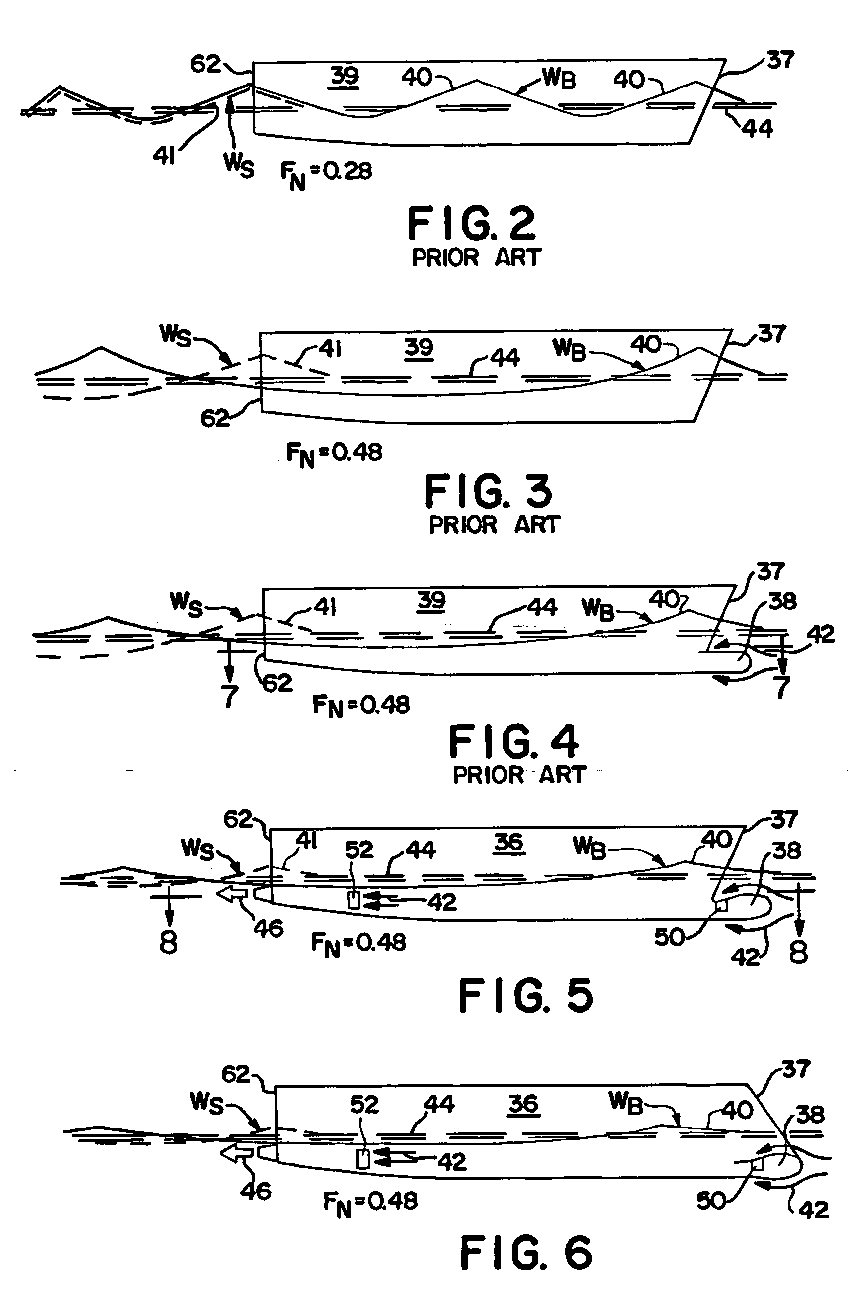
[0058]FIG. 2 presents typical wave patterns for a typical prior art ship 39. These are presented at a Fn of 0.28 which corresponds to speeds of about 18 knots for the 400 foot (122 meter) LWL ship and 28 knots for the 800 foot (244 meter) LWL ship. No...


PUM


Abstract

Presented is a water propulsion systern for ships that enhances the efficiency of both the water propulsor(s) and the ship itself. This is accomplished by location of water inlet(s) for the water propulsor(s) to take advantage of water flow characteristics around a secondary bow of the ship and also proximal a stern of the ship. A primary object is to reduce the energy of the bow and/or stern waves of the ship and hence reduce the ship's wave making resistance. A secondary object is to reduce the frictional resistance of the ship. The water propulsors are preferably electrically driven with built in stator field windings and armatured rotors. A bow oriented water propulsor(s) would preferably have its discharge into a gas cavity in the underside of the ship. Both bow oriented and stern oriented water propulsor(s) would optimally have steering and/or reversing mechanisms.

Description

RELATED UNITED STATES DATA [0001] This application is a continuation-in-part of Ser. No. 10 / 827,568 filed Apr. 19, 2004, now abandoned, and Ser. No. 10 / 846,127 filed May 14, 2004.BACKGROUND OF THE INVENTION [0002] Displacement hull ships are very efficient with high Lift / Drag (L / D) ratios up to a point where a very large wave drag component takes president. This is clearly shown upon examination of FIG. 1 of this application that shows the two predominant hydrodynamic resistance or drag components for typical displacement hull ships. These two drag components are friction drag and wave drag. It can be noted from FIG. 1 that friction drag is the predominant drag force up to about 18 knots for a ship with a waterline length of 400 feet (122 meters) and up to about 27 knots for a ship with a waterline length of 800 feet (244 meters). As speed is increased beyond those values, powering requirements become excessive for all practical purposes. [0003] Various attempts have been made to re...

Claims


Application Information

Patent Timeline
Patent Type & Authority Applications(United States)
IPC IPC(8): B63B1/34
CPCB63B1/38B63B1/40Y02T70/125Y02T70/121Y02T70/122B63H11/08Y02T70/10
Inventor BURG, DONALD E.
Owner BURG PAULETTE RENEE
Why Eureka
Try Eureka