Corrugated tube fitting

a technology of corrugated tubes and fittings, which is applied in the direction of fluid pressure sealing joints, hose connections, mechanical equipment, etc., can solve the problems of limited ability to tighten parts, lack of precision in cutting the end of the tubing, and range of known fittings, etc., to achieve good mechanical strength and sealing performance, the effect of minimal complexity and expens

Active Publication Date: 2006-01-12
HIGHLANDS CORP
View PDF24 Cites 57 Cited by
  • Summary
  • Abstract
  • Description
  • Claims
  • Application Information

AI Technical Summary

Benefits of technology

[0020] It is an object of the invention to provide a fitting for use in various forms of corrugated tubing terminations and couplings, having good mechanical strength and sealing performance compared to known fittings, with minimal complexity and expense. It is another object to provide a metal-to-metal seal that is formed simply by threading together a fitting on a cut end of tubing without needing extreme torque to form a seal that depends on the pressure exerted between clamping surfaces. Instead it is an object to obtain metal / metal sealing upon achieving a particular state of assembly that can be felt by the assembler.

Problems solved by technology

Known fittings have a range of structures and complexity.
In a seal in which parts are threaded together to clamp down onto the tubing, there is a minimum tightness needed to achieve a seal, and there is a limit as to how far the parts can be tightened.
Also, a lack of precision in cutting the end of the tubing (such as defects in the smoothness of the cut edge, alignment of the cut of the plane normal to the axis of the tube, and the like) do not defeat sealing if the dimensional irregularity is less than or equal to the compression of the gasket.
Compressible gaskets also have drawbacks.
Compressible materials for gaskets are generally less durable than metal, particularly the stainless steel of a corrugated tube.
Compression can permanently compress and otherwise damage compressible gasket material, making the fitting unsuitable for re-use after detachment.
Compressible materials may be damaged by heat, combustion or exposure to chemicals.
Compressible materials may complicate assembly because it is necessary to achieve a certain compression force, but it may damage a gasket to over-tighten and crush the gasket.
The correct amount of compression is difficult for the assembler to assess by feel.
Tolerances associated with the precision of metal surfaces can be important because metals are not readily compressible.
These variations complicate the possibility of a direct endwise seal between the cut end and an abutting surface arranged substantially in a plane normal to the axis of the tube.
Although not relying on extreme torque to seal, the fitting should also achieve a tightness whereby the fitting is difficult or impossible to unthread manually without the use of tools.

Method used


Image

  • Corrugated tube fitting
  • Corrugated tube fitting
  • Corrugated tube fitting

Examples


Embodiment Construction

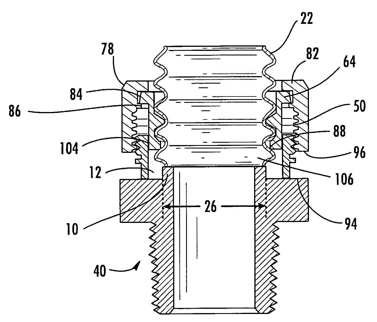
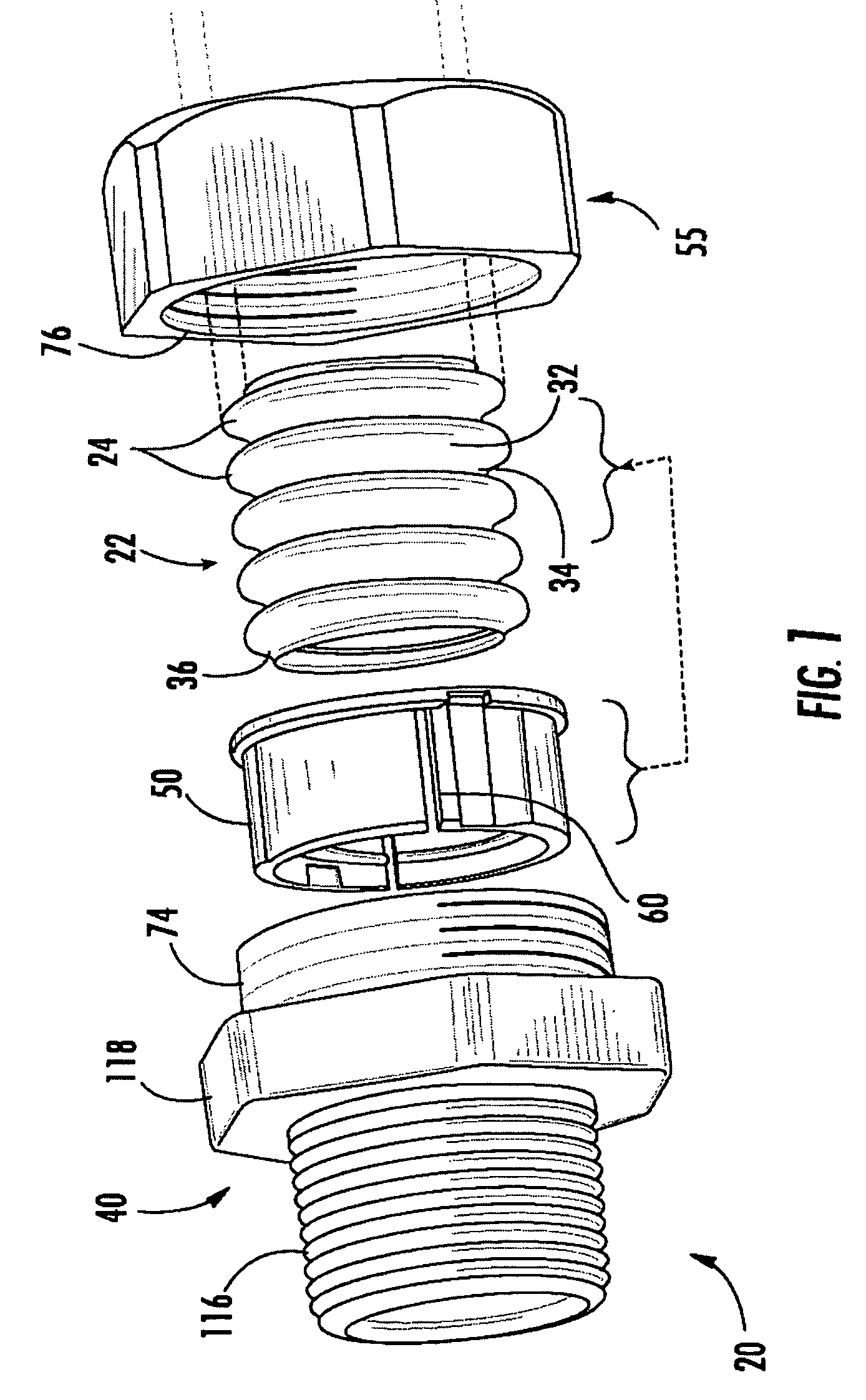
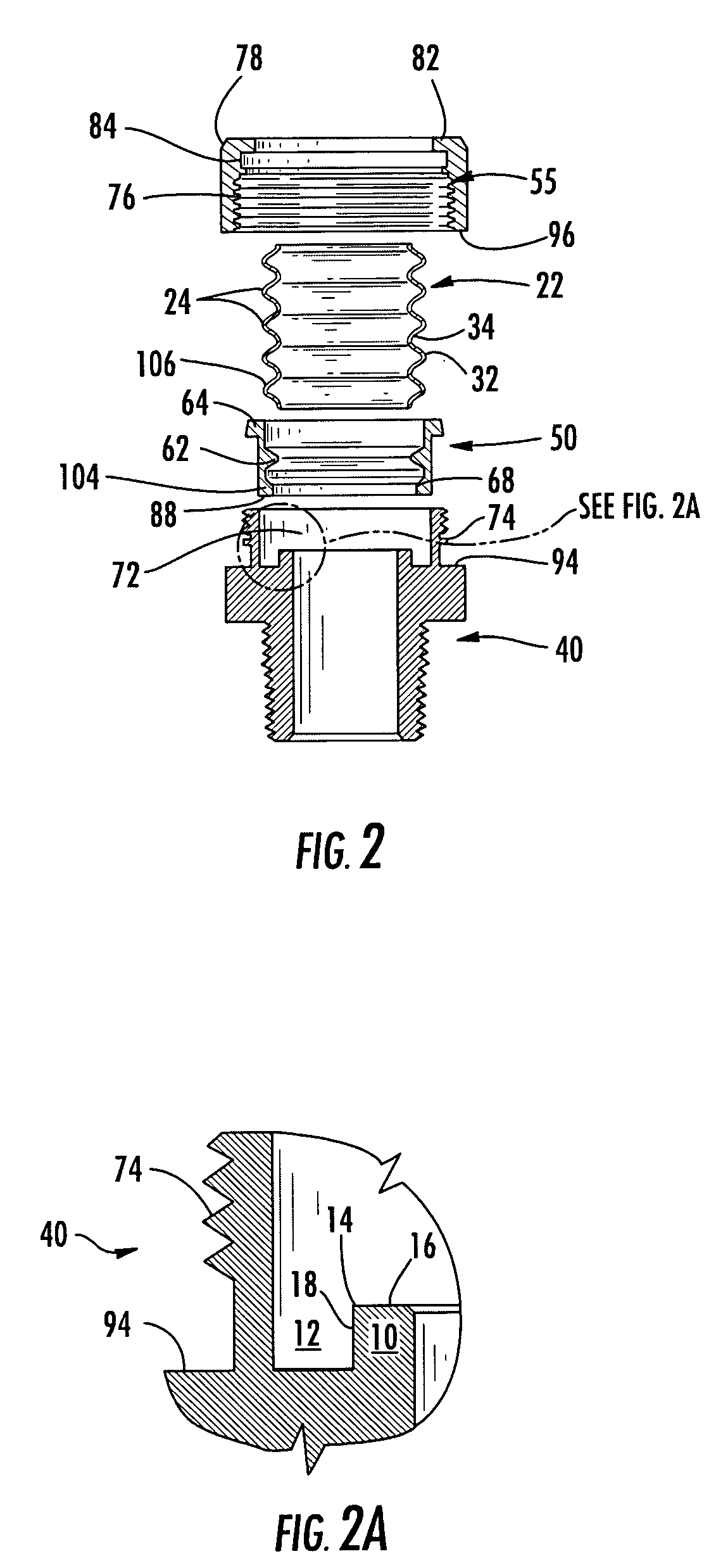
[0039] An inventive fitting 20 for an end of a length of tubing 22 such as corrugated stainless steel tubing is shown in FIGS. 1-7, which include exemplary variations as discussed herein. FIG. 1 shows the respective parts in an exploded view as a cut end of a length of tubing of indefinite length, to be terminated by fitting 20. The termination can be for any of the various purposes that might benefit from a sealed connection to the tubing, especially mechanical attachment and hermetic sealing.

[0040] In the non-limiting example shown in FIG. 1, the fitting forms a union between the tubing and a pipe thread on a generally cylindrical fitting body 40. This sort of union is typically used for making a connection between the flexible corrugated tubing and a fixed pipe, manifold, apparatus housing or other station disposed along a flow path for gas or fluid in communication with tubing 22. The fitting body 40 has a tapered thread facing away from tubing 22 and wrench flats. The inventio...


PUM

PropertyMeasurementUnit
angleaaaaaaaaaa
cross sectional angleaaaaaaaaaa
lengthaaaaaaaaaa

Abstract

A fitting for an end of a length of corrugated tubing forms a gas-tight metal-to-metal seal by rolling and folding an endmost corrugation into a axially extending annular groove in the fitting body. A ridged retainer grips the tubing corrugations above the endmost corrugation and is axially advanced into the fitting body by a nut. The cut end at the endmost corrugation of the tubing encounters the axially facing end of a tubular stub inside the fitting body and folds over itself and into the annular groove between the stub and the inside surface of the fitting body. A seal member is thus formed with a pair of substantially parallel sealing surfaces, and resides between the retainer and the outside surface of the tubular stub. The seal member forms a metal/metal seal with the tubular stub.

Description

BACKGROUND OF THE INVENTION [0001] 1. Field of the Invention [0002] The invention concerns a fitting for sealed termination of a length of corrugated tubing, especially corrugated stainless steel gas lines, of the type that includes a generally cylindrical fitting body and nut, threaded together on opposite sides of a tubing retainer. The retainer has one or more inward rings or ridges, complementary with the tubing corrugations. The retainer grips the corrugated tubing near a cut end. Tightening the nut on the fitting body forces the retainer to advance the cut end of the tube axially into the fitting body. [0003] According to an inventive aspect, the cut end is carried by the retainer against an axially facing surface in the fitting body surrounded by an annular groove. The annular groove is sized to receive the end of the retainer, with a slight annular clearance approximating the thickness of the tubing material. The endmost corrugation ridge is folded over into the annular groo...

Claims


Application Information

Patent Timeline
Patent Type & Authority Applications(United States)
IPC IPC(8): F16L33/00
CPCY10S285/903F16L25/0036
Inventor WATANABE, TARO
Owner HIGHLANDS CORP
Why Eureka
Try Eureka