LCD panel including gate drivers

a technology of gate drivers and lcds, applied in the field of lcds, can solve the problems of lcds using the dot inversion driving method being rarely used in portable terminals, high power consumption, and deterioration of lcds, so as to prevent flickering of images displayed and reduce power consumption

Active Publication Date: 2006-01-12
SAMSUNG ELECTRONICS CO LTD
View PDF35 Cites 76 Cited by
  • Summary
  • Abstract
  • Description
  • Claims
  • Application Information

AI Technical Summary

Benefits of technology

[0017] The present invention provides an apparatus that drives gate lines in such a way that power consumption is reduced and flickering of an image displayed is prevented, and a liquid crystal display (LCD).

Problems solved by technology

When an electric field is continuously applied to the LCD in one direction, characteristics of the LCD deteriorate due to inherent characteristics of a liquid crystal material.
In addition, since data lines are driven at large amplitude in the dot inversion driving method, high power consumption is required.
Thus, LCDs using the dot inversion driving method are seldom used for portable terminals.
Therefore, a difference in liquid crystal transmittance of two frames is easily recognized, causing the screen to flicker.
Thus, the frame inversion driving method is rarely used.
However, since the polarity of the common voltage Vcom is inverted for each gate line, high power consumption is required.
Such high power consumption puts an LCD using the line inversion driving method at a great disadvantage when the LCD is to be used in portable devices constrained by power.
However, since the polarity of the common voltage Vcom is inverted every n adjacent lines, the n-line inversion driving method results in flickering.
On the other hand, a 3-line inversion driving method consumes 1.47 mA.
However, when the 2 or more line inversion driving method is used, a number of adjacent lines have the same polarity, and thus the problem of flickering emerges.

Method used


Image

  • LCD panel including gate drivers
  • LCD panel including gate drivers
  • LCD panel including gate drivers

Examples


Embodiment Construction

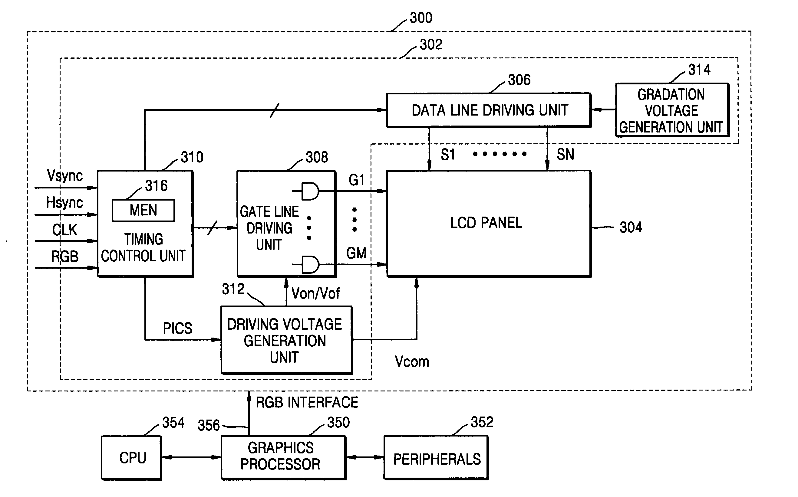
[0036] The present invention will now be described more fully with reference to the accompanying drawings, in which exemplary embodiments of the invention are shown. The invention may, however, be embodied in many different forms and should not be construed as being limited to the embodiments set forth therein; rather, these embodiments are provided so that this disclosure will be thorough and complete, and will fully convey the concept of the invention to those skilled in the art. Like reference numerals in the drawings denote like elements, and thus their description will omitted.

[0037]FIG. 3 is a block diagram of a liquid crystal display (LCD) 300 and its surrounding circuitry according to an embodiment of the present invention. Referring to FIG. 3, the LCD 300 receives image data from a graphics processor 350 via a red, green, and blue (RGB) interface 356. The graphics processor 350 receives data from a central processing unit (CPU) 354 and peripherals 352 such as a camera and ...


PUM


Abstract

Provided is a liquid crystal display panel having gate drivers. The LCD panel includes a gate line shift circuit setting a gate line scanning order such that the gate lines are sequentially scanned in units of n gate lines with k-1 gate lines between each pair of adjacent gate lines in each unit according to an interleaving method in response to a gate line-on signal received from a timing control unit outside the LCD panel, wherein the LCD panel reproduces source data output from a source driver outside the LCD panel in the gate line scanning order set by the gate line shift circuit. The LCD panel inverts the polarity of a common voltage for every unit of n gate lines, instead of every gate line, thereby reducing power consumption. In addition, since every kth gate line is scanned according to the interleaving method, deterioration of image quality such as a flickering phenomenon can be prevented, which is an advantage of a line inversion driving method.

Description

BACKGROUND OF THE INVENTION [0001] This application claims the priority of Korean Patent Application No. 10-2004-0051145, filed on Jul. 1, 2004, in the Korean Intellectual Property Office, the disclosure of which is incorporated herein in its entirety by reference. [0002] 1. Field of the Invention [0003] The present invention relates to a liquid crystal display (LCD), and more particularly, to a driving unit and a timing controller which control an LCD to drive gate lines included in the LCD in units of a predetermined number of gate lines, and a driving method used by the LCD. [0004] 2. Description of the Related Art [0005] A conventional liquid crystal display (LCD) applies an adjustable voltage to a material having an anisotropic permittivity injected between two substrates to adjust the amount of light transmitted through the substrates, thereby obtaining a desired image. The LCD includes a plurality of scan lines transmitting gate select signals and a plurality of data lines cr...

Claims


Application Information

Patent Timeline
Patent Type & Authority Applications(United States)
IPC IPC(8): G09G3/36
CPCG09G3/3614G09G3/3648G09G3/3666G09G2330/021G09G2310/0213G09G2310/0224G09G2320/0247G09G3/3677G09G3/36
Inventor KANG, WON-SIKKIM, SEONG-CHEOLJANG, SUNG-JINWOO, JAE-HYUCKCHOI, CHULCHUNG, KYU-YOUNG
Owner SAMSUNG ELECTRONICS CO LTD
Why Eureka
Try Eureka