Optical disk writing apparatus

a writing apparatus and optical disk technology, applied in the direction of digital signal error detection/correction, instruments, recording signal processing, etc., can solve the problems of complex control, difficult to correct output properly, complex control, etc., and achieve the effect of simple configuration and reduced error ra

Inactive Publication Date: 2006-01-12
FUNAI ELECTRIC CO LTD
View PDF6 Cites 1 Cited by
  • Summary
  • Abstract
  • Description
  • Claims
  • Application Information

AI Technical Summary

Benefits of technology

[0015] In view of the foregoing, an object of the present invention is to provide an optical disk writing apparatus that can maintain appropriate write power in real time with a simple configuration (as a result, the recording quality is improved to allow reduction in the error rate even for media with lower fabrication quality).
[0017] Accordingly, the period of time during which data writing must be conducted concurrently with data reading can be set to zero. By eliminating such a period, control can be provided in a more real-time manner. Further, error correction is allowed. By virtue of error correction, the requirement of confirming whether the data has been read properly or not at every reading of data can be relieved. Accordingly, the configuration of the detector can be set more simple while maintaining real-time control. Furthermore, the energy density employed at the time of the laser oscillator writing data onto an optical disk can be controlled appropriately. Thus, an optical disk writing apparatus that can maintain appropriate write power in a more real-time manner with a more simple configuration can be provided.
[0019] Since data can be read out during intervals between data writing, the configuration of the detector is simplified. The energy density to be employed at the time of the writing device writing data onto the optical disk is controlled appropriately. Further, real-time control is allowed. This is because evaluation by the evaluation processor can be conducted between intervals of data supply by the supply circuit. Thus, an optical disk writing apparatus that can maintain appropriate write power in real time with a simple configuration can be provided.
[0021] Accordingly, the period of time during which data writing must be conducted concurrently with data reading can be set to zero. Elimination of such a period allows control in a more real-time manner. Thus, an optical disk writing apparatus that can maintain appropriate write power in a more real-time manner with a simple configuration can be provided.
[0023] Accordingly, the data read out can be handled more easily. This provides the advantage that the configuration of the detector can be set more simple while allowing real-time control. Thus, an optical disk writing apparatus that can maintain appropriate write power in a more real-time manner with a simpler configuration can be provided.
[0025] Since the correction processor corrects the error, the requirement of confirming whether data has been read out properly or not at every data read out is relieved. Accordingly, the configuration of the detector can be set more simple while maintaining real-time control. Thus, an optical disk writing apparatus that can maintain appropriate write power in a more real-time manner with a simpler configuration can be provided.

Problems solved by technology

Running OPC is disadvantageous in that it is difficult to correct the output properly when the period of time of emission of a laser beam is short since control becomes complex.
The approach of irradiating an optical disk with at least two laser beams, and correcting the recording power of the first laser beam based on the asymmetry value of an RF signal read out by the second laser beam, as disclosed in Japanese Patent Laying-Open No. 2001-312822, is disadvantageous in that control becomes complex.
Therefore, the control will become complex when the intensity of the laser beam is to be controlled for recording based on a plurality of laser beams.
Therefore, there is a problem that the output of the optical pickup is not optimum.
Such an approach involves the problem that optimization of the laser output is still required to be further improved.

Method used


Image

  • Optical disk writing apparatus
  • Optical disk writing apparatus
  • Optical disk writing apparatus

Examples


Embodiment Construction

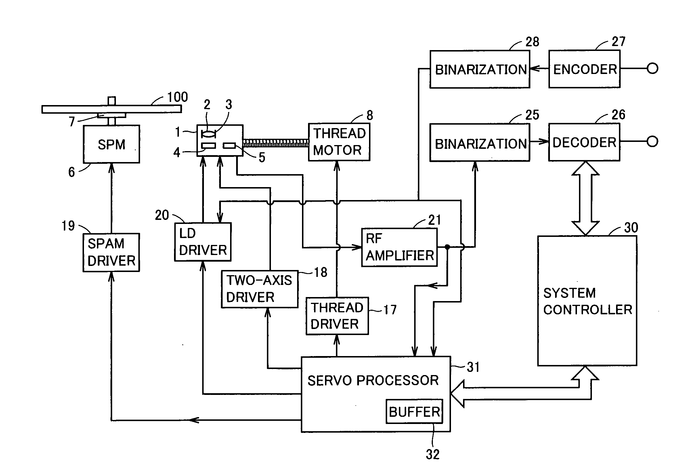
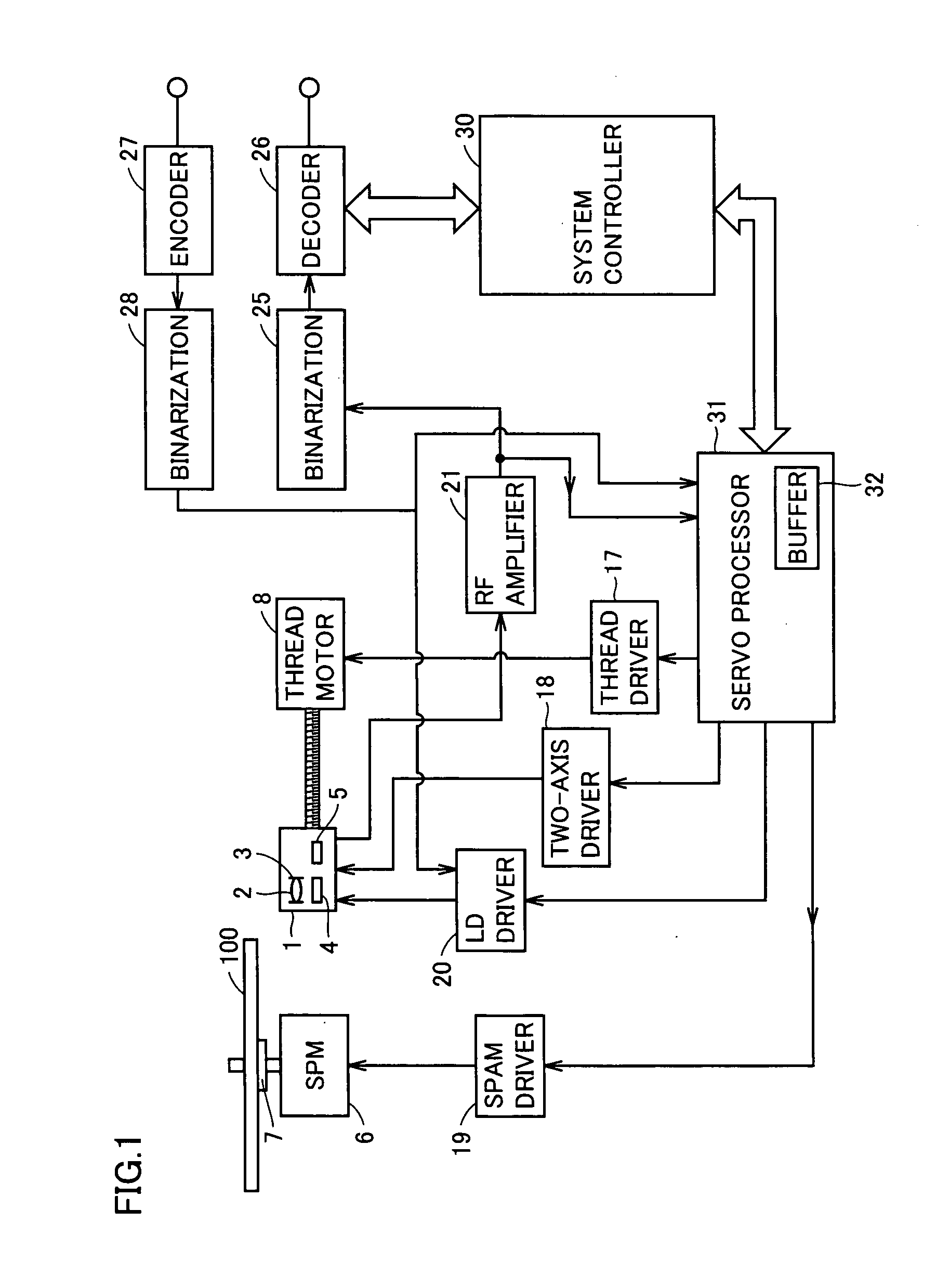
[0035] Referring to FIG. 1, an optical disk writing apparatus according to an embodiment of the present invention includes a turntable 7 on which a DVD (Digital Versatile Disk) 100 identified as an optical disk is mounted, a spindle motor 6 for rotating turntable 7, a spindle motor drive 19 for driving spindle motor 6, an optical pickup 1 to emit a laser beam towards DVD 100, an LD (Laser Diode) driver 20 to operate emission of a laser beam by optical pickup 1, a two-axis driver 18 including a focus driver and a tracking driver for optical pickup 1, a thread motor 8 for the operation of optical pickup 1, a thread driver 17 to control thread motor 8, an RF amplifier 21 to amplify the RF signal of a reproduced signal output from optical pickup 1, a binarization circuit 25 for binarizing the RF signal output from RF amplifier 21, a decoder 26 decoding a signal subjected to binarization to output reproduction data, an encoder 27 encoding recording data to be recorded onto DVD 100, a bin...


PUM

PropertyMeasurementUnit
energy densityaaaaaaaaaa
timeaaaaaaaaaa
poweraaaaaaaaaa

Abstract

An optical disk writing apparatus maintaining appropriate write power in real time with a simple configuration includes a buffer for recording data, a binarization circuit supplying data to the buffer, an LD writing data recorded in the buffer onto a DVD disk, a detector reading out from the DVD disk a signal representing data written by the LD at an arbitrary time during a period starting from when the amount of data recorded in the buffer and not yet written onto the DVD disk becomes zero until the amount of data reaches a predetermined number of ECC blocks, and a servo processor correcting an error in the data read out by the detector for every data amount susceptible to error correction at one time, evaluating the writing of the LD using the corrected signal, and controlling the energy density to be employed in writing data onto the DVD disk by the LD according to its own evaluation.

Description

BACKGROUND OF THE INVENTION [0001] 1. Field of the Invention [0002] The present invention relates to optical disk writing apparatuses, and particularly, to an optical disk writing apparatus that can control output. [0003] 2. Description of the Related Art [0004]“Write Pause” refers to a standby status of output during a recording operation of an optical pickup. In a conventional optical pickup, the level of output is modified to the output obtained by OPC (Optical Power Control) when output is to be adapted to a writing state. It cannot be said that the output of the optical pickup in such a case is optimum. Accordingly, there is developed a method to correct the output of the optical pickup concurrently with the actual recording operation (running OPC). [0005] Running OPC is disadvantageous in that it is difficult to correct the output properly when the period of time of emission of a laser beam is short since control becomes complex. In view of such a problem, various methods of c...

Claims


Application Information

Patent Timeline
Patent Type & Authority Applications(United States)
IPC IPC(8): G11B15/52
CPCG11B7/1263
Inventor TSUKADA, SEIJI
Owner FUNAI ELECTRIC CO LTD
Why Eureka
Try Eureka