Data recovery circuits using oversampling for maverick edge detection/suppression

a data recovery circuit and edge detection technology, applied in the direction of amplitude demodulation, code conversion, pulse technique, etc., can solve the problems of complex and expensive solutions, sporadic perturbations, and add a delay to the data stream, so as to achieve full and simple digital circuit integration

Inactive Publication Date: 2006-01-12
IBM CORP
View PDF2 Cites 15 Cited by
  • Summary
  • Abstract
  • Description
  • Claims
  • Application Information

AI Technical Summary

Benefits of technology

[0008] It is another object of the present invention to provide improvements to data recovery circuits using o

Problems solved by technology

In addition to jitter and ISI, some sporadic perturbations can occur to add a delay on the data stream.
As result, this solution is complex and expensive because it consumes a lot of silicon area when the data recovery cir

Method used


Image

  • Data recovery circuits using oversampling for maverick edge detection/suppression
  • Data recovery circuits using oversampling for maverick edge detection/suppression
  • Data recovery circuits using oversampling for maverick edge detection/suppression

Examples


example 1

[0039] 1111101111111111

[0040] Example 2 represents E′ values for single data rate (SDR) data with jitter. The transition position varies in time due to the presence of jitter, so that more than one data transitions are detected.

example 2

[0041] 111000111111111

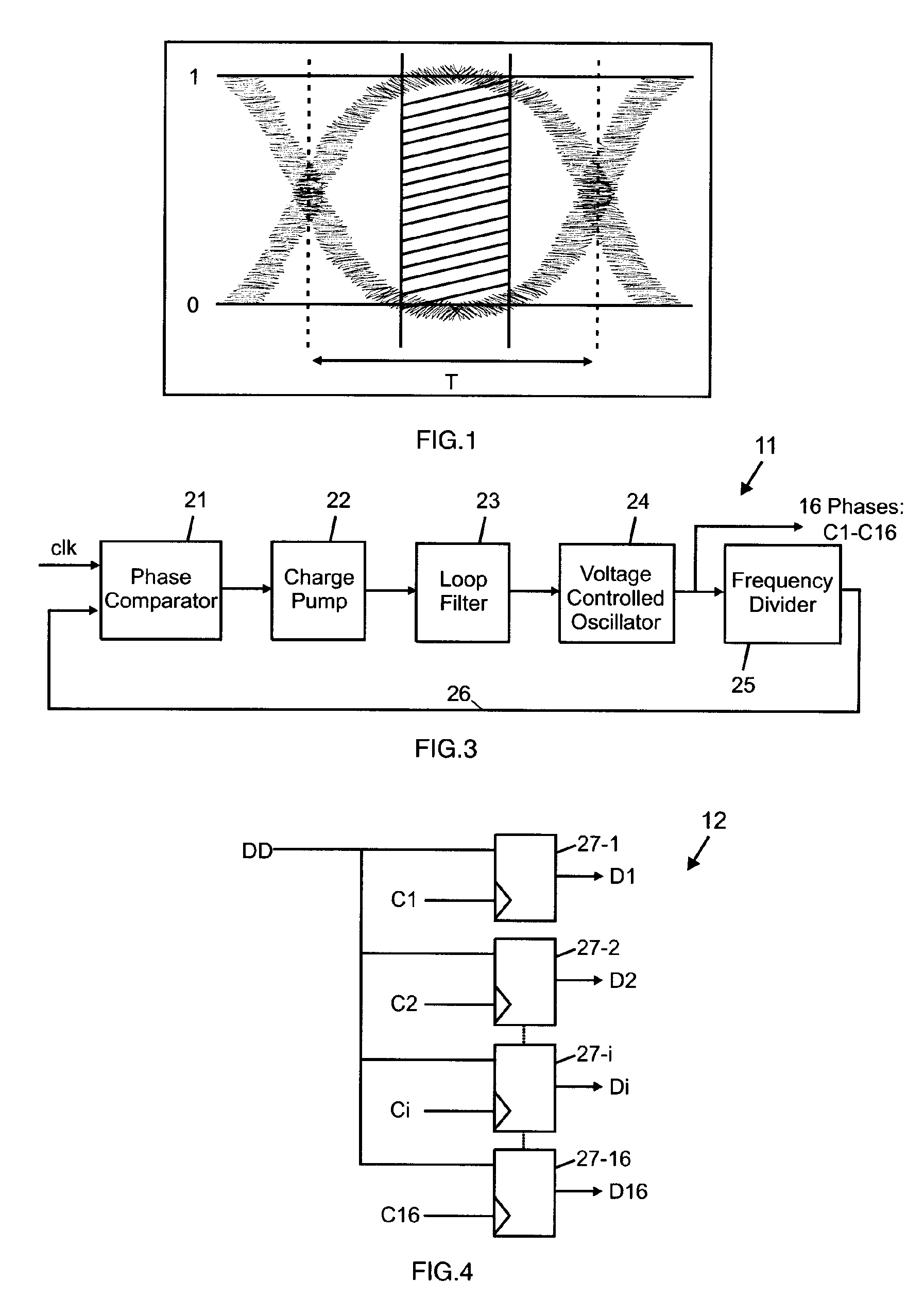
[0042] The zone filled with ‘0’s corresponds to the grayed zone in the eye diagram of FIG. 1.

[0043] Example 3 represents E′ values for double data rate (DDR) data without jitter. As there are now two bits of data per clock period, two data transition positions were detected.

example 3

[0044] 1111101111111011

[0045] Example 4 represents E′ values for DDR data with jitter. The presence of jitter on the incoming data stream has the effect of moving the detected data edge randomly around a central position. The effect on the E′ values is to increase the width of the zones with adjacent ‘0’s.


PUM


Abstract

A data recovery circuit employing an oversampling technique. The incoming serial data stream with jitter is oversampled by means of the multiple phases of a reference clock to produce data samples. Each sample is compared to the samples collected with the next clock phase in an edge detector circuit to determine the presence of a data edge. The edge information, representative of the data edge positions, is stored and accumulated in the form of a bit map. A detection/suppression circuit detects and suppresses edges which are not adjacent to any other edge in the edge memory. A selection determination circuit uses the edge information to indicate which sample is the farthest from the data edges. A selection validation circuit validates the selection to avoid false determination due to jitter and skew.

Description

FIELD OF THE INVENTION [0001] The present invention relates to high speed serial communications / data transfers between integrated circuits or systems and more particularly to improvements to data recovery circuits based on an oversampling technique for maverick edge detection and suppression. BACKGROUND OF THE INVENTION [0002] In the field of high speed serial communications / data transfers between integrated circuits or systems, data recovery circuits are extensively used in transceivers. The performance of a data recovery circuit is intimately tied to its capacity to correctly recover the transmitted data when the clock period varies with time. It must also be able to deal with any type of troubles introduced by transmission channel artifacts as well as by modulation and pulse shaping components in the transmission paths. Therefore, to sustain high data rate, the data recovery circuit must be able to deal with these data perturbations usually referred to respectively as the jitter ...

Claims


Application Information

Patent Timeline
IPC IPC(8): H04L7/00
CPCH04L7/0338
Inventor VALLET, VINCENTMALCAVET, DIDIER
Owner IBM CORP
Why Eureka
Try Eureka