Acousto-optic device

a technology of optical devices and acoustical beams, applied in the field of acoustical beams, can solve the problems of limited range of tunable optical wavelengths to which mode conversion is performed, difficult to extend the range of tunable optical wavelengths, and the limitation of the frequency range of directional coupling type acousto-optic devices, etc., to achieve the effect of completely coupling the frequency range of the frequency range of the directional coupling devi

Inactive Publication Date: 2006-01-12
FUJITSU LTD
View PDF2 Cites 1 Cited by
  • Summary
  • Abstract
  • Description
  • Claims
  • Application Information

AI Technical Summary

Benefits of technology

[0033] Like this, according to the present invention, a plurality of electrodes configured so as to correspond to a frequency band to be generated as a surface acoustic wave are provided, which provides an advantage that a frequency band which can be generated as a surface acoustic wave can also be extended.
[0034] In particular, according to the present invention, the electrodes comprise of a plurality of pairs of comb electrodes, and said pairs of comb electrodes have distances between teeth different from each other, corresponding to a frequency band to be generated as a surface acoustic wave propagating in said surface acoustic wave propagation unit, which provides an advantage that a frequency band which can be generated as a surface acoustic wave can also be extended by extending the frequency band of RF signals which can be supplied for excitation of surface acoustic waves.
[0035] Furthermore, according to the present invention, a plurality of pairs of comb electrodes configured so as to correspond to a frequency band to be generated as a surface acoustic wave are so configured, corresponding to a frequency band to be generated as a surface acoustic wave which propagates in the surface acoustic wave guide, so as to be able to generate a surface acoustic wave having a different kind of mode order from each other, which provides an advantage that a frequency band of SAWs being able to be excited can be extended to a (high frequency) range to which it has not conventionally been extended.

Problems solved by technology

However, an acousto-optic device like the AOTF 100 shown in FIG. 17 described above has a problem that because of a limitation on a band which can be generated as a SAW, when it is used as an AOTF, there is a limitation on the range of tunable optical wavelengths to which mode conversion is performed, so that it is difficult to extend the range of tunable optical wavelengths.
Because of this, a directional coupling type acousto-optic device also has a limitation on the frequency range of SAWs based on the range of frequencies coupling completely.
This limitation on SAW wavelength is directly linked to the limitations of optical wavelengths to which mode conversion is possible.

Method used


Image

  • Acousto-optic device
  • Acousto-optic device
  • Acousto-optic device

Examples


first embodiment

[A1] First Embodiment

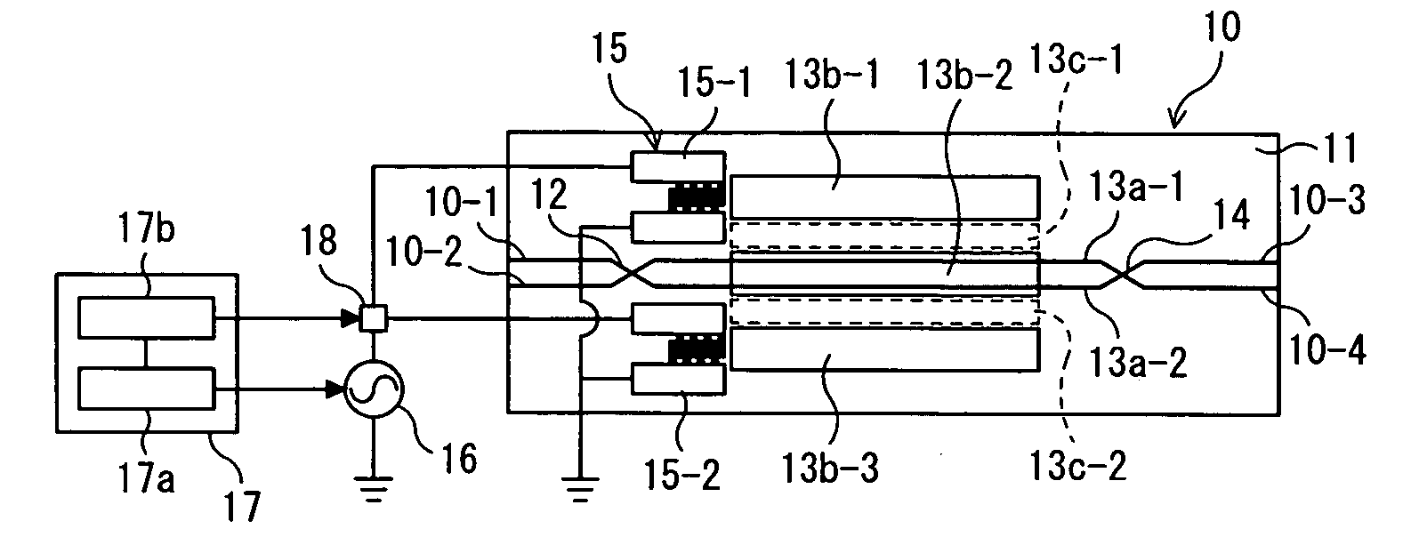
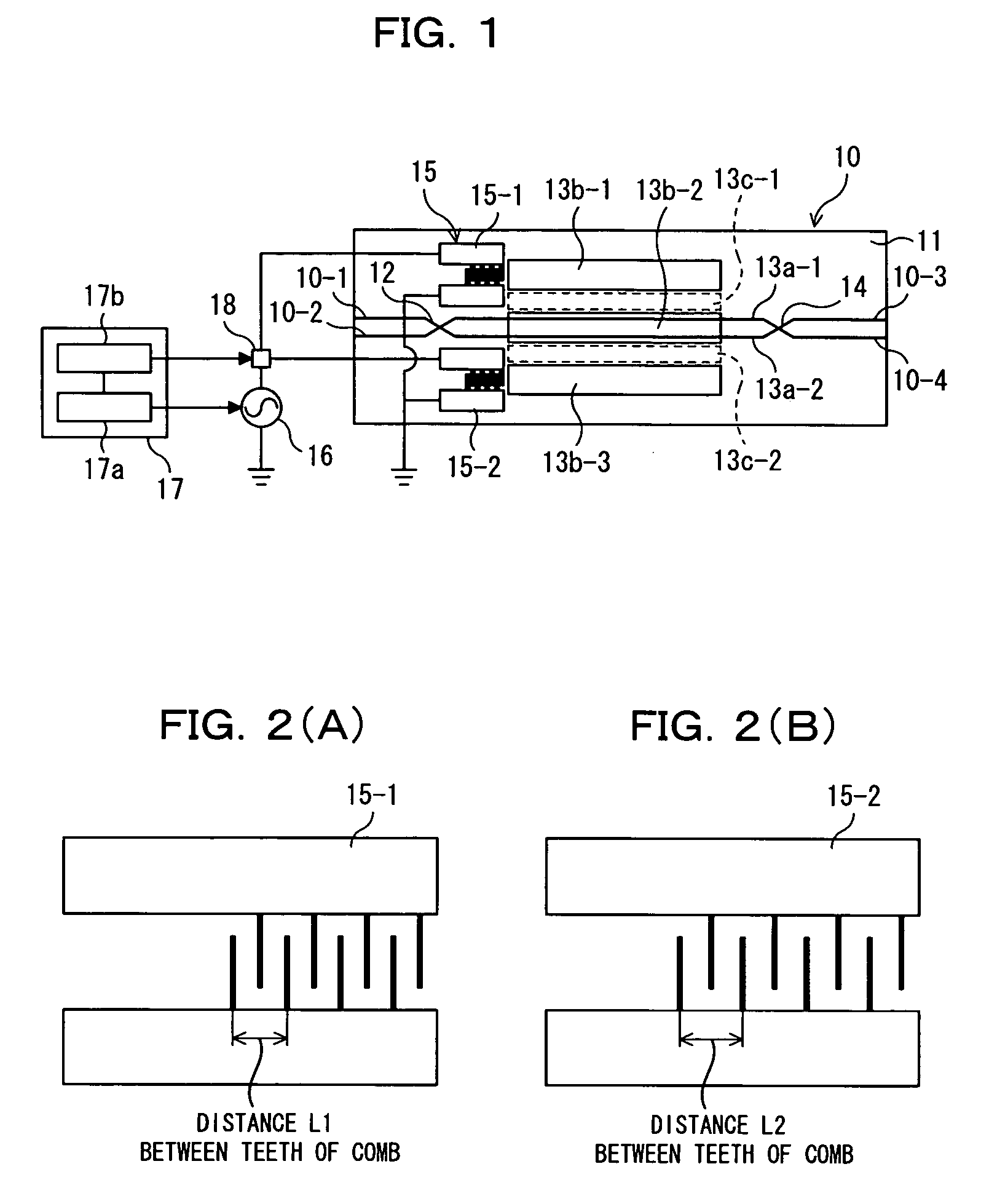
[0060]FIG. 1 shows an acousto-optic device according to the first embodiment of the present invention. The acousto-optic device 10 shown in FIG. 1 is provided with a substrate 11 having birefringence and acousto-optic effect such as an LN substrate on which polarization beam splitters 12, 14, two parallel optical waveguides 13a-1, 13a-2, surface acoustic wave guides 13b-1 to 13b-3, and a transducer electrode unit 15 are formed, and is designed to be able to be used as an acousto-optic tunable filter (AOTF) for example.

[0061] In the figure, reference numeral 16 denotes an RF electric source as an electric signal source capable of generating an electric signal (RF signal having RF frequency) to be applied to the transducer electrode unit 15, reference numeral 17 denotes an RF signal control unit capable of controlling the apply of an electric signal from the RF electric source 16 to the transducer electrode unit 15, and reference numeral 18 denotes a change-over ...

second embodiment

[B2] Variation of Second Embodiment

[0141]FIG. 15 shows an acousto-optic device 30A according to a variation of the second embodiment of the present invention, and FIG. 16 shows a pair of comb electrodes 35A-2 which is the main part of the acousto-optic device 30A. The acousto-optic device 30A shown in FIG. 15 is different from the acousto-optic device 30 according to the second embodiment described above in the configuration of the transducer electrode unit 35A and in the method of supplying an RF signal to the transducer electrode unit 35A.

[0142] That is, in the second embodiment described above, the transducer electrode unit 35 comprises the pair of comb electrodes 35-2 which is so formed that the interdigitation pattern of the tooth electrodes 32a, 32b is opposite to that of the tooth electrodes 32c, 32d in order to excite a SAW of higher order mode. However, as a variation, the pair of comb electrodes 35A-2 may be configured as shown in FIGS. 15 and 16 for example.

[0143] In th...


PUM

PropertyMeasurementUnit
surface acoustic waveaaaaaaaaaa
frequencyaaaaaaaaaa
phasesaaaaaaaaaa

Abstract

The present invention relates to an acousto-optic device capable of extending the frequency band of SAWs being able to be generated by it, the acousto-optic device comprising: a light propagation unit for propagating light; a surface acoustic wave propagation unit capable of propagating a surface acoustic wave causing interaction with light which propagates in the light propagation unit; and a transducer electrode unit provided with a plurality of electrodes configured so as to correspond to a frequency band to be generated as the surface acoustic wave which propagates in the surface acoustic wave propagation unit.

Description

BACKGROUND OF THE INVENTION [0001] 1) Field of the Invention [0002] The present invention relates to an acousto-optic device suitably used in an optical communication system. [0003] 2) Description of the Related Art [0004] An acousto-optic device is a device utilizing an acousto-optic effect that is an interaction between an ultrasonic wave and light, such as an Acousto-Optic Tunable Filter (AOTF). This AOTF is expected to be used for an optical cross connect, an optical switch, light modulation, or the like in addition to an Optical Add-Drop Multiplexer (OADM) in a Wavelength Division Multiplexing (WDM) optical communication system. [0005] An acousto-optic wavelength tunable filter is a wavelength filter using a TE-TM mode conversion caused by an acousto-optic effect that is an interaction between light in an optical waveguide made on a piezoelectric material such as a lithium niobate (LiNbO3) substrate (hereinafter simply referred to LN substrate in some cases), and a Surface Acou...

Claims


Application Information

Patent Timeline
Patent Type & Authority Applications(United States)
IPC IPC(8): G02F1/335G02B6/42
CPCG02F2201/124G02F1/125
Inventor TSUNODA, YUKITOMIYATA, HIROSHI
Owner FUJITSU LTD
Why Eureka
Try Eureka