Method for manufacturing disposable rotary cutting tools and disposable rotary tool for dental or medical applications
- Summary
- Abstract
- Description
- Claims
- Application Information
AI Technical Summary
Benefits of technology
Problems solved by technology
Method used
Image

Examples
first embodiment
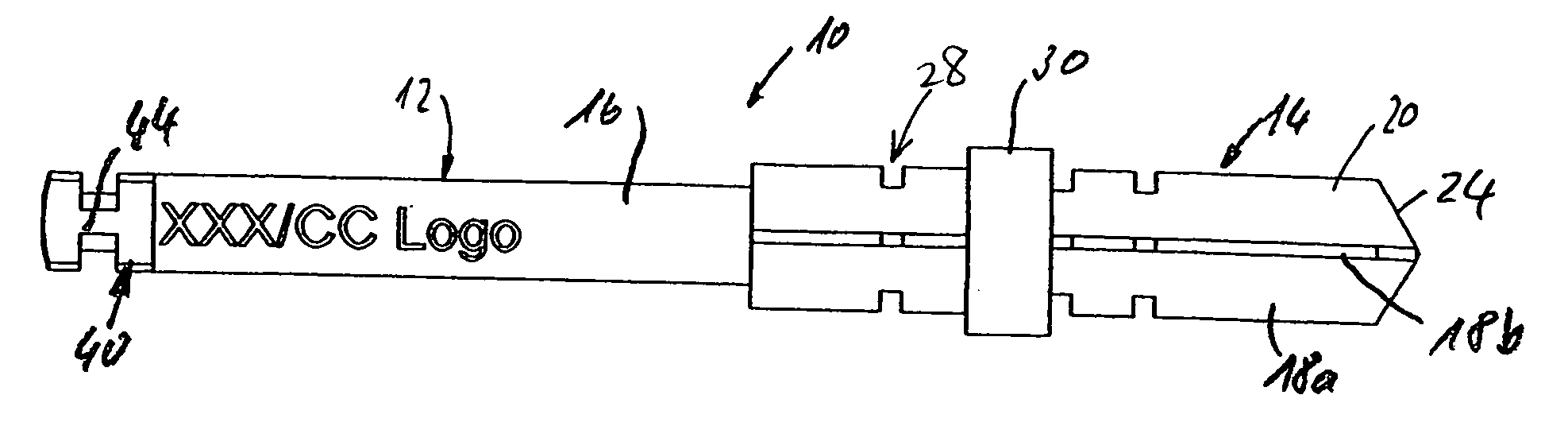
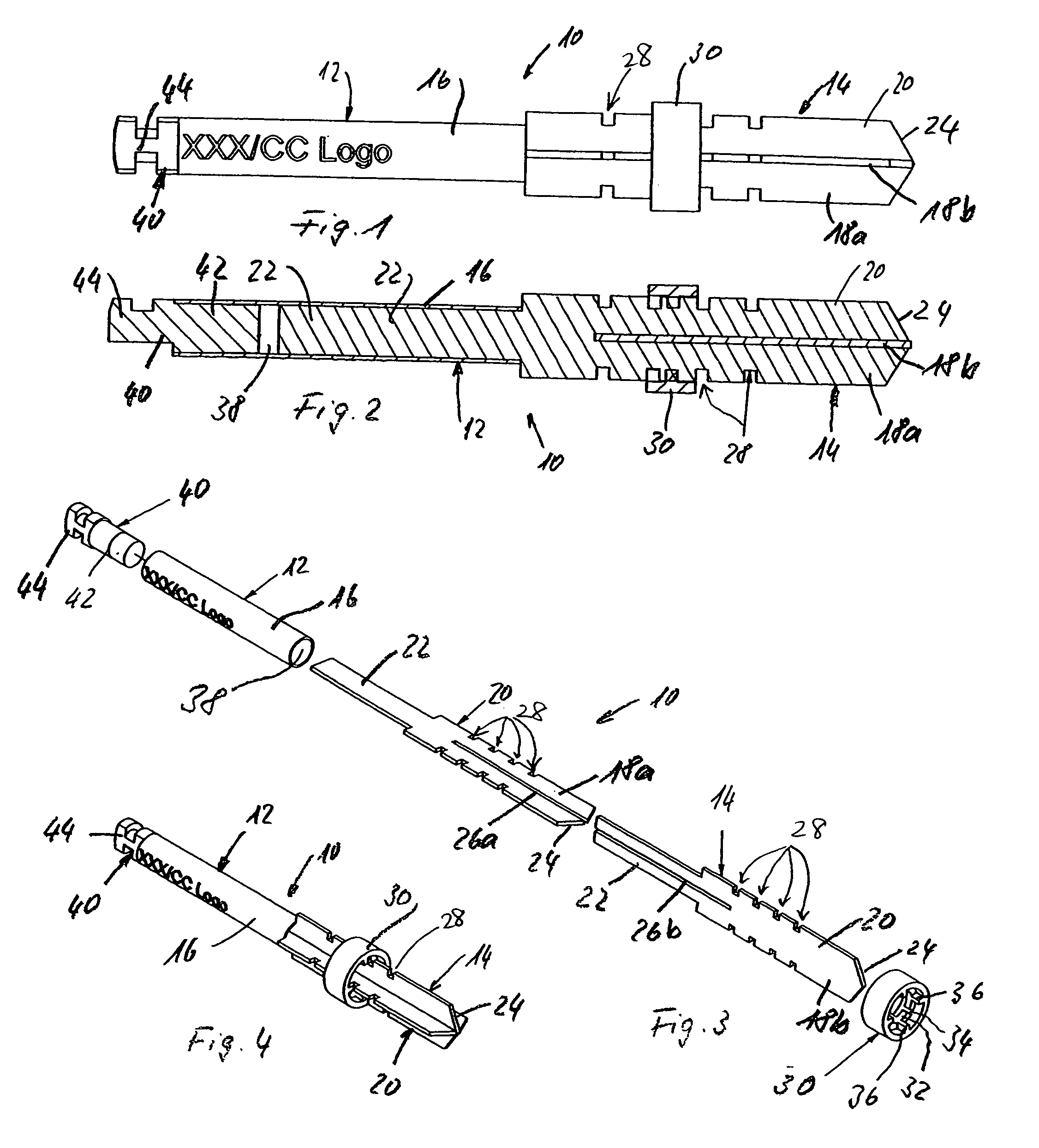
[0053] a cutting tool 10 shown in FIGS. 1 to 4 comprises a tool shank 12 and a tool head 14. The tool shank 12 consists of a pipe section 16 cut from a drawn metal pipe. The shell of the pipe section 16 is parameterized and branded.
[0054] The tool head 14 is formed by two cut-outs 18 of a drawn metal sheet, that are arranged in a crosswise manner. The cut-outs 18a, 18b are detached form the metal sheet by non-cutting machining, for example by punching. The thereby produced sharp edges are not further machined.
[0055] The cut-outs 18a, 18b have an essentially rectangular formed working portion 20 and an adjacent integral rectangular fastening portion 22. A front edge 24 of the working portion 20 is indeed formed to a vertex whereby the front edge portions enclose an obtuse angle.
[0056] Furthermore, the cut-outs 18a, 18b comprise complementary slots 26a, 26b, i.e. the cut-out 18a has a slot 26a running along a central axis of the cut-out 18a from the front end of the cut-out 18a to t...
sixth embodiment
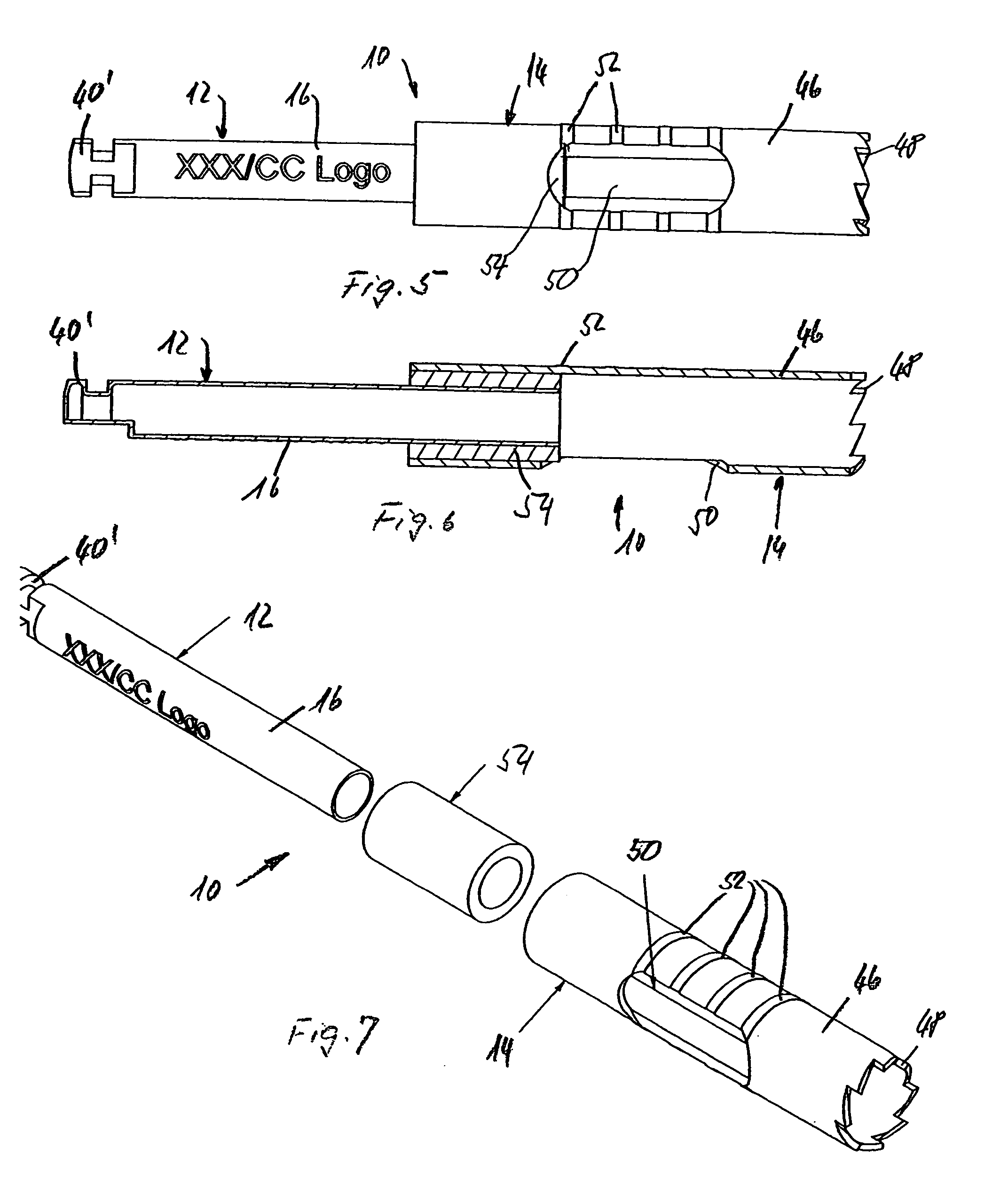
[0073] the cutting tool 10 shown in FIGS. 17 to 19 comprises a further pipe section 56 with an integrally formed fastening connector part 40′ of the same design as the pipe section 16 shown in FIGS. 5 to 7. This further pipe section 56 is force fittingly driven into the pipe section 16 of the same design as the pipe section shown in FIGS. 8 to 10 and 14 to 16 with the exception of the absent monitoring window 50.
[0074] The tool head consists of two cut-outs 18a, 18b with a rectangular working portion 20 and a rectangular fastening portion 22 with a width greater than the outer diameter of the pipe section 16 and the width of the working portion 20. Consequently slots 26a and 26b of the cut-outs 18a, 18b allow the cross-wise engagement of the cut-outs 18a, 18b as already described in connection with the embodiment shown in FIGS. 1 to 4.
[0075] The cut-outs 18a, 18b further comprise lateral slots 64 beginning at the rear end of the fastening portion 22, running in the axial direction ...
seventh embodiment
[0077] the cutting tool 10 shown in FIGS. 20 to 22 comprises an identical further pipe section 56 as the cutting tools of FIGS. 8 to 13 and 17 to 19. The further pipe section 16 shown in FIGS. 20 to 24 does not comprise protuberances and a monitoring window; it is simply a section sawn from a drawn pipe.
[0078] The tool head 14 consist of two cut-outs 18a, 18b with complementary slots 26a and 26b attached in a cross-wise manner. Furthermore, the cut-outs 18a, 18b comprise lateral slots 64—as described in connection with the FIGS. 17 to 19—for the collet of the wall of the pipe section 16. In contrast to the embodiment of FIGS. 17 to 19, the cut-outs 18a, 18b of the present embodiment comprise a fastening portion 20, the inner part of which—arranged in the duct 38 of the pipe section—is longer than the outer part.
PUM
| Property | Measurement | Unit |
|---|---|---|
| Force | aaaaa | aaaaa |
| Deformation enthalpy | aaaaa | aaaaa |
Abstract
Description
Claims
Application Information
 - R&D
- Intellectual Property
- Life Sciences
- Materials
- Tech Scout
- Unparalleled Data Quality
- Higher Quality Content
- 60% Fewer Hallucinations
Browse by: Latest US Patents, China's latest patents, Technical Efficacy Thesaurus, Application Domain, Technology Topic, Popular Technical Reports.
© 2025 PatSnap. All rights reserved.Legal|Privacy policy|Modern Slavery Act Transparency Statement|Sitemap|About US| Contact US: help@patsnap.com