Manipulable input device with adjustable magnetorhelogical motion damper

a technology of magnetorhelogical motion and input device, which is applied in the field of input devices, can solve the problems of large size of prior damping devices using mr fluid, and is not well suited to smaller input devices, and achieve the effect of altering the viscosity of mr fluid

Inactive Publication Date: 2006-01-12
DELPHI TECH INC
View PDF11 Cites 26 Cited by
  • Summary
  • Abstract
  • Description
  • Claims
  • Application Information

AI Technical Summary

Benefits of technology

[0008] The present invention provides an improved method and apparatus for damping an input device, through the use of a damping element adapted for attachment between a support, and an input element of the input device, which is configured for receiving an input through manipulation of the input element by a user. The input generates a movement of the input element. The damping element includes a cavity forming element and a magnetizable element. The cavity forming element defines one or more cavities containing a magnetorheological (MR) fluid. The magnetizable element is disposed at a position adjacent the MR fluid for impressing a magnetic field on the MR fluid, to thereby alter the viscosity of the MR fluid and damp the movement of the input element generated by the input.

Problems solved by technology

The need to provide the movable piston, and to make the piston physically large enough so that it can include the holes and electrical coils, has caused prior damping devices using MR fluid to generally be relatively large, and not well suited to smaller sized input devices.

Method used


Image

  • Manipulable input device with adjustable magnetorhelogical motion damper
  • Manipulable input device with adjustable magnetorhelogical motion damper
  • Manipulable input device with adjustable magnetorhelogical motion damper

Examples


Embodiment Construction

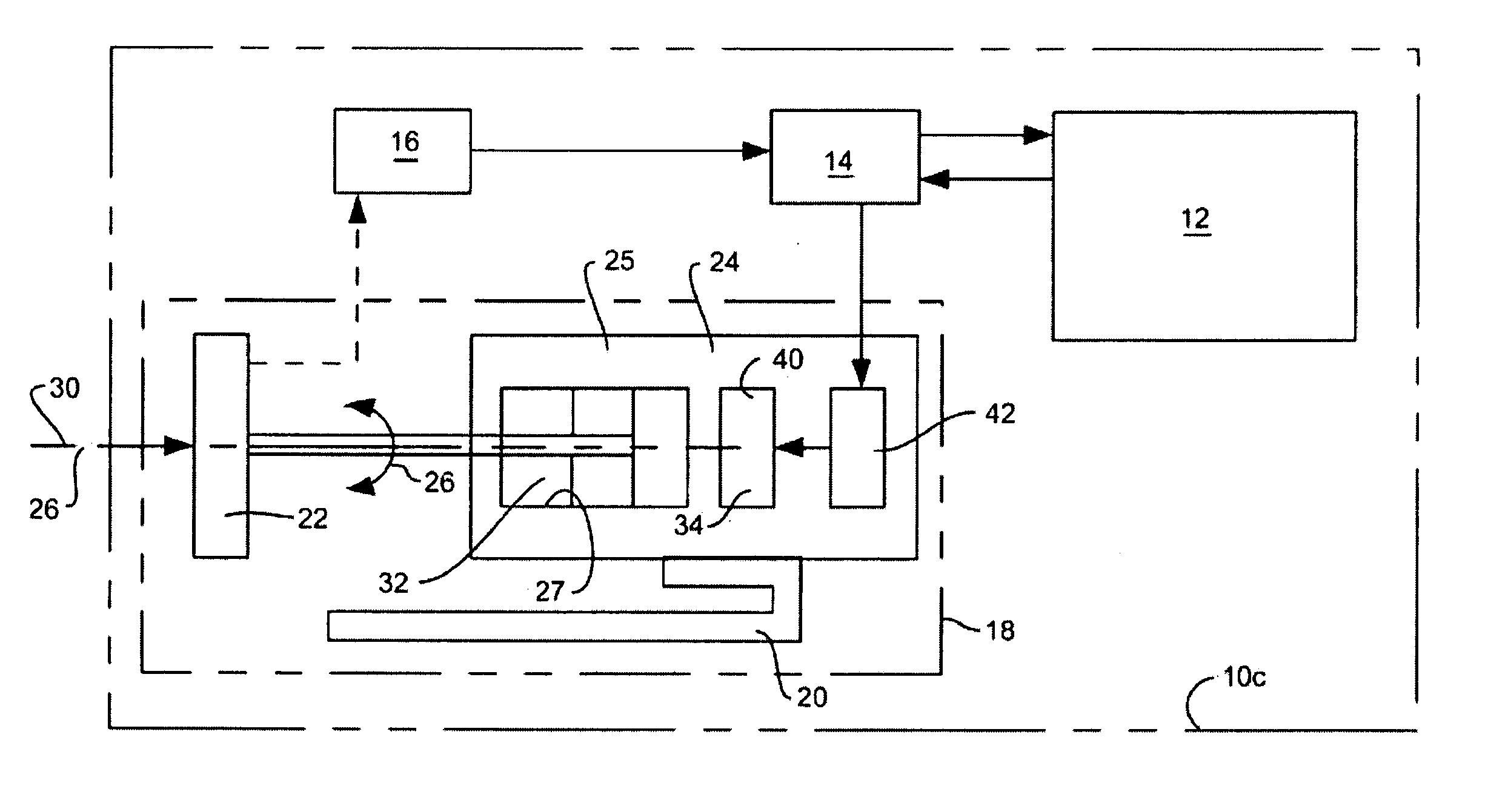
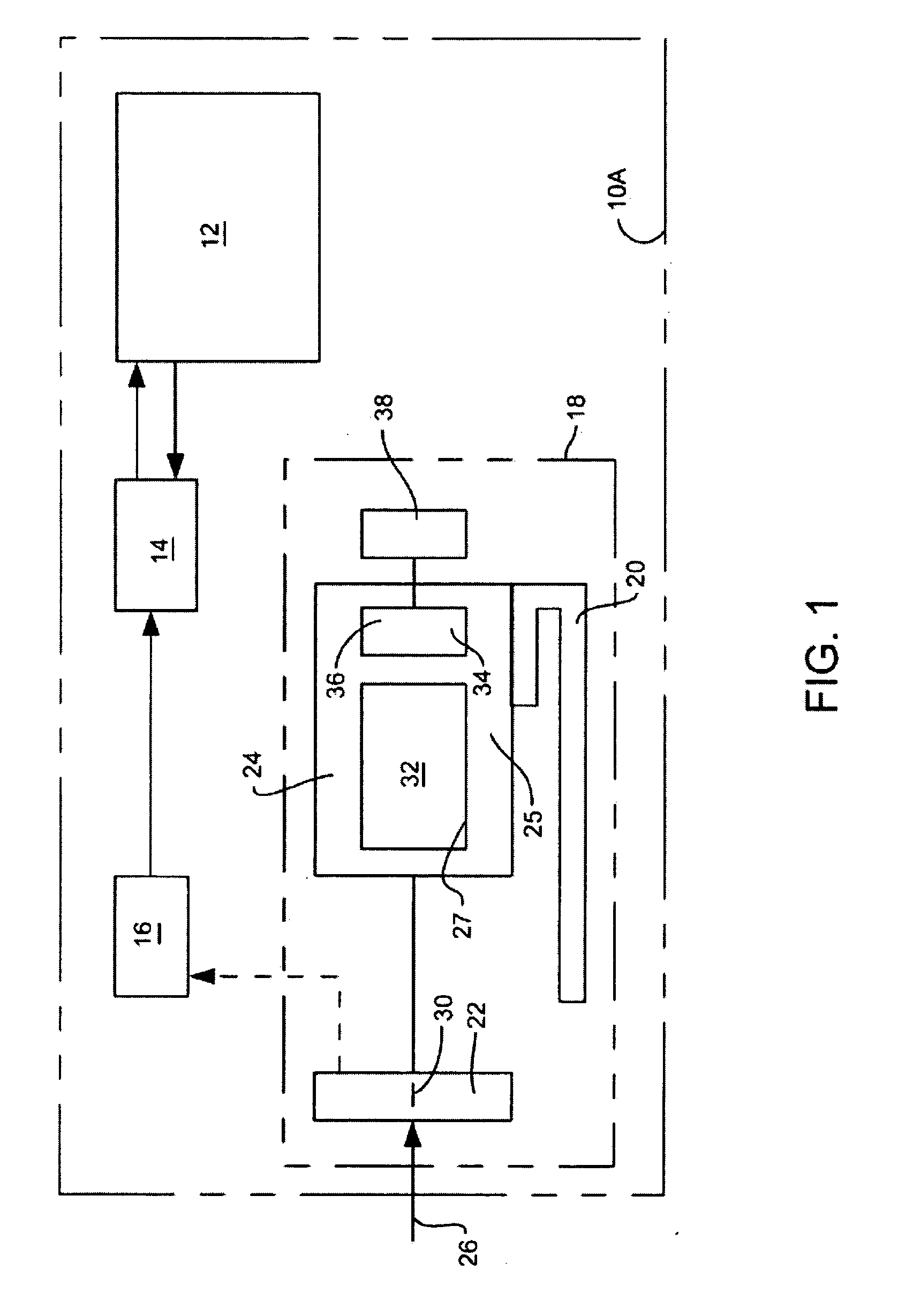
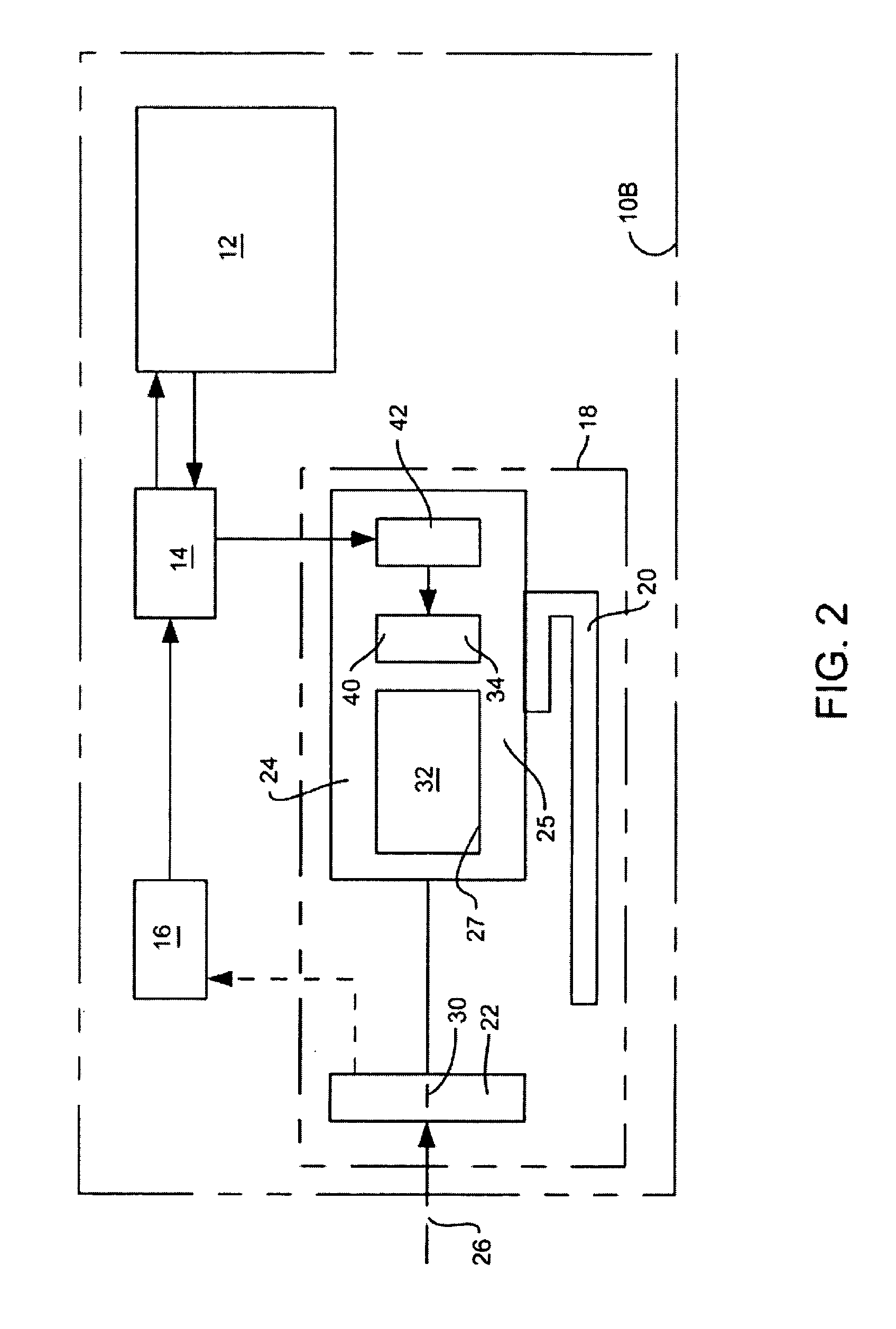
[0028]FIGS. 1-3 show three exemplary embodiments of a control system 10a, 10b, 10c, each including a controlled device 12, a controller 14, a sensor 16, and an exemplary embodiment of the invention in the form of an input device 18, including a support 20, an input element 22, and a damping element 24.

[0029] In each of the exemplary control systems 10a, 10b, 10c, the input element 22 is configured for receiving an input, through manipulation of the input element 22 by a user, for generating a movement of the input element 22. As described in more detail below, an input device 18 and damping device 24 of the invention can be configured for operation with inputs that are linear, rotary, a combination of linear and rotary, or applied obliquely to the input element 22. In the input devices 18 of FIGS. 1 and 2, the input is linearly directed, as indicated by arrows 26, along an axis 30 of the input element 22. In the input device 18 of FIG. 3, the input may be directed either linearly, ...


PUM


Abstract

A method and apparatus for damping an input device, utilizes a damping element attached between a support and an input element of the input device. The damping element includes a cavity forming element and a magnetizable element. The cavity forming element defines one or more cavities containing a magnetorheological (MR) fluid. The magnetizable element is disposed at a position adjacent the MR fluid for impressing a magnetic field on the MR fluid, to thereby alter the viscosity of the MR fluid and damp the movement of the input element generated by the input. In some embodiments, the damper includes a compliant element with a porous segment having one of the one or more cavities therein containing the MR fluid, with the compliant member having a stiffness. Application of the magnetic field to the MR fluid changes the stiffness of the compliant member.

Description

TECHNICAL FIELD OF THE INVENTION [0001] This invention relates to input devices for providing control inputs to a machine, and more particularly to providing damping of movement of such input devices to provide a desired tactile feel for a user of the control device. BACKGROUND OF THE INVENTION [0002] It is common practice to utilize an input device, such as a keypad, joystick, a hand or thumb wheel, foot pedal, or lever, for communicating an input command to a machine, such as a computer, video game, a medical device, a robotic system, or other types of control systems. [0003] It is also known to utilize some form of damping of the input, in such control devices, to provide a desired tactile feel or force feedback through the input device to the user. For example, U.S. Pat. No. 6,486,872, to Rosenberg, et al, discloses a method and apparatus for providing passive force feedback. [0004] Prior input devices utilize a variety of types of damping devices, including hydraulic dampers us...

Claims


Application Information

Patent Timeline
Patent Type & Authority Applications(United States)
IPC IPC(8): B60G17/018G06F17/00
CPCF16F9/535
Inventor PAWLAK, ANDRZEJ M.PANKIN, JAYSON D.GOMES-CASSERES, GLENN
Owner DELPHI TECH INC
Why Eureka
Try Eureka