
Apparatus for processing a fluid sample

a fluid sample and apparatus technology, applied in the direction of fluid controllers, chemistry apparatus and processes, laboratory glassware, etc., can solve the problems of inability to meet the needs of non-skilled laboratory workers, and inability to process fluid samples in a non-laboratory environmen

Inactive Publication Date: 2006-01-19
THE SEC OF STATE FOR DEFENCE IN HER BRITANNIC MAJESTYS GOVERNMENT OF THE UK OF GREAT BRITAIN & NORTHERN IRELAND
View PDF3 Cites 52 Cited by
  • Summary
  • Abstract
  • Description
  • Claims
  • Application Information

AI Technical Summary

Benefits of technology

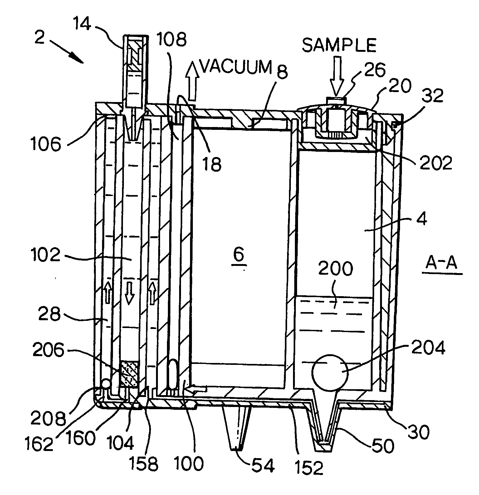
[0036] It is preferred in the apparatus of the present invention to utilise a combination of both a means for generating a vacuum and a means for applying force behind the fluid to move fluid from at least one of the further chambers through the sample processing chamber and into the waste chamber. The use of the two together has the advantage that the initial force behind the fluid initiates release of the fluid from any given chamber that the vacuum could direct the fluid flow through the apparatus thus preventing it from being diverted from the desired path. This enables the apparatus to be readily designed such that fluid can flow sequentially from the further chambers through the sample processing chamber according to a pre-determined protocol.
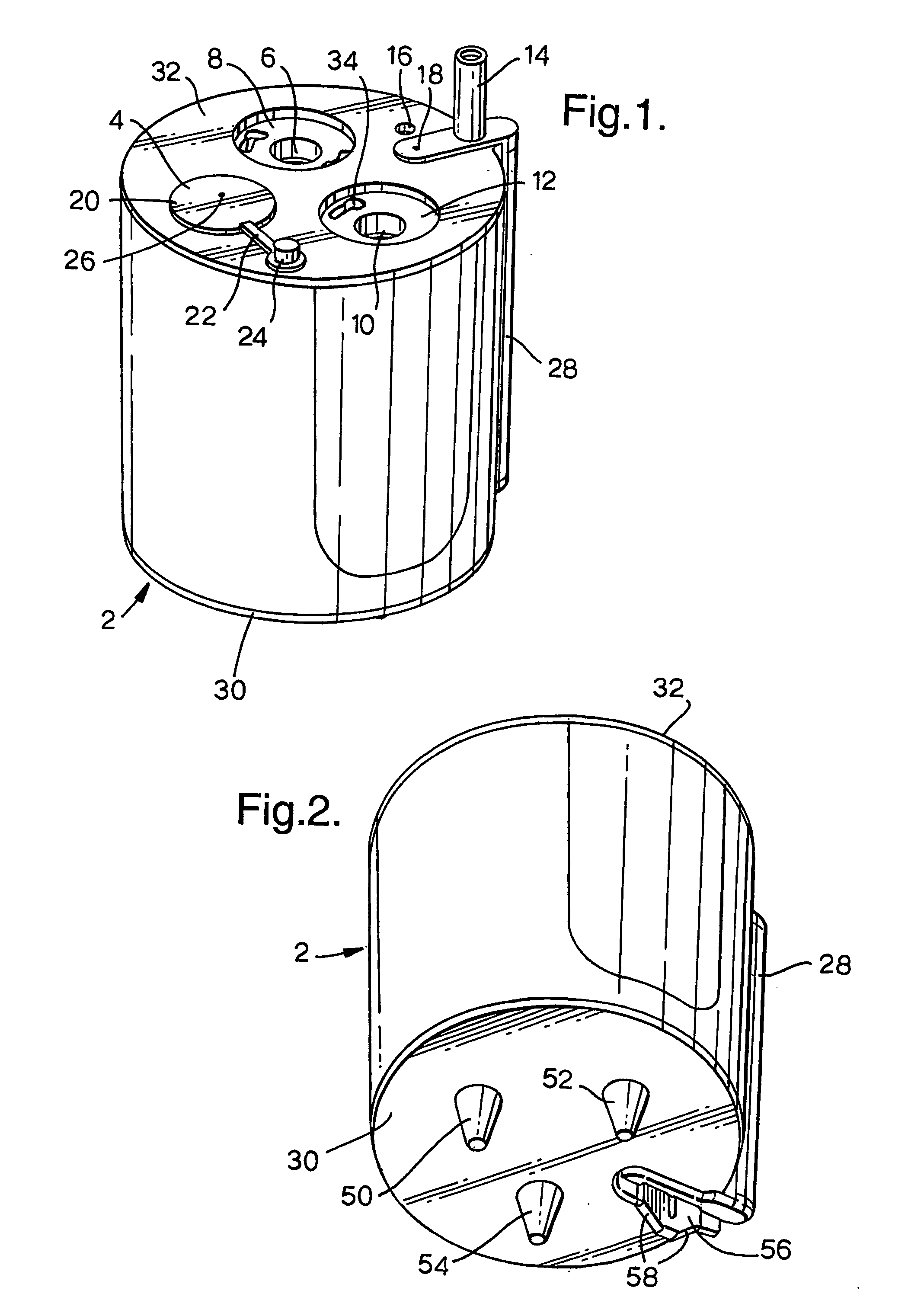
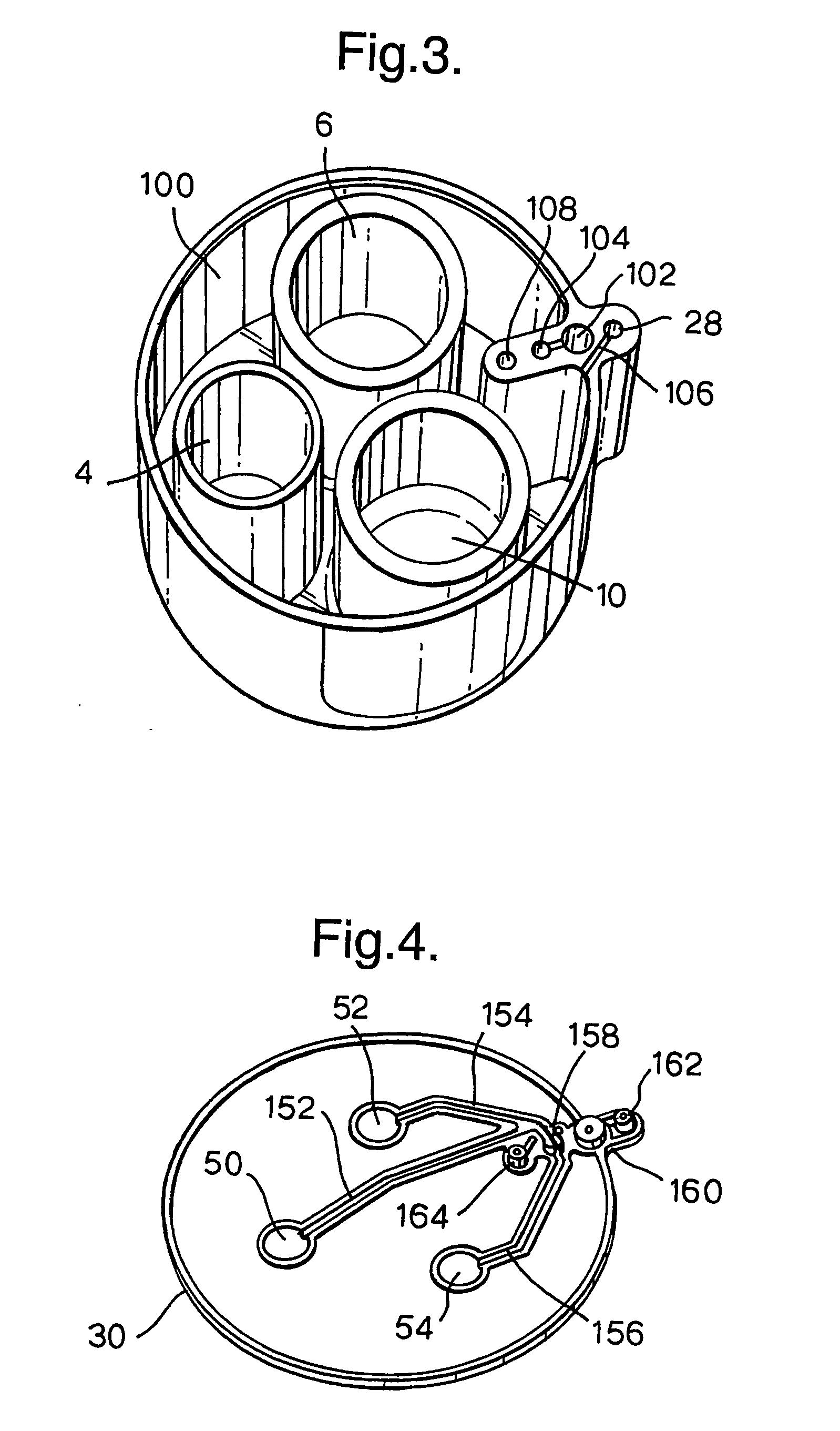
[0051] Additionally the apparatus may integrate with a mechanical apparatus. This could be for several reasons including for applying the means for moving the fluid using a physical apparatus, such as the vacuum or plunger depression, or for subjecting one or more of the chambers of the apparatus to a physical processing step for example thermal, optical or acoustical processing, sensing or monitoring. If such integration is required it is important to ensure that the apparatus is designed such that it can integrate effectively with such an additional physical apparatus. It is also important to ensure that such an integration is as simple as possible such that it can effectively be used by a non-skilled worker. This may include designing the apparatus such that it can only be integrated in a single orientation, using colour coding to aid the orientation and the like.

Problems solved by technology

Although nucleic acid amplification, for example the polymerase chain reaction (PCR) is a very useful and commonly used method for positive identification of biological material, several problems exist when trying to successfully develop it for use on a day to day basis for the rapid identification of biological material in many individual fluid samples in a non-laboratory environment, for example to achieve near patient or point of care disease diagnosis.
One of the key problems lies in the fact that, prior to subjecting a typical clinical or environmental sample to nucleic acid amplification, it needs to undergo a sequence of processing steps using reagents, some of which are hazardous, to purify and concentrate the biological material.
However, there are several problems associated with these methods.
These include that they are slow, resource intensive, expensive, subject to error and to cross sample contamination.
In addition, conventional fluid processing systems require fluid samples to flow sequentially through a series of different chambers where each chamber is utilised for a single step in a sequence which may result in loss of sample, and automation of such processes requires the use of complex fluidic assemblies and processing algorithms.
Although this provides a development in the field of an apparatus for processing a fluid sample, several problems remain.
One such problem is that, in order to expose the fluid sample sequentially to different solutions, it is necessary to rotate the valve body to connect in turn, via several external ports, a sample processing chamber with a reservoir of each solution.
Such an apparatus is not well suited for use in a non-laboratory environment by a non-skilled laboratory worker because, for among other reasons, there is a need to connect the external ports to reservoirs of each required solution which is impractical and in the case of hazardous chemicals may be a safety risk.
In addition such an apparatus, due to its complexity, has a high associated cost, and is unlikely to be cost effective as a disposable apparatus and that result in the potential for cross sample contamination.
Furthermore, the apparatus utilises a single fluid displacement chamber to deliver each processing solution to the sample in turn, and to remove any waste materials, which may result in mixing of residual material in the fluid displacement chamber and potential failure of sensitive processing sequences.
Such an apparatus is useful for conducting nucleic acid amplification reactions on micro-scale volume samples but the problem remains as to how to develop such an apparatus which can be used in the field wherein the volume of the sample is several millilitres as is the case for clinical or environmental samples.
Again this apparatus presents a development in the field of processing a fluid sample but several problems remain.
Furthermore this complex arrangement may result in some sample remaining inside the fluid cartridge thereby reducing the amount of sample that is ultimately processed.
This can lead to inaccurate results in the case of high volumes of sample which retain a low concentration of the desired analyte.
Finally the complexity of the cartridge makes the apparatus more difficult to operate in the field by the unskilled user.

Method used


Image

  • Apparatus for processing a fluid sample
  • Apparatus for processing a fluid sample
  • Apparatus for processing a fluid sample

Examples


Embodiment Construction

[0024] All publications cited herein are hereby incorporated by reference in their entirety, unless otherwise indicated.

[0025] As used herein the term “fluid communication” means that a path through which fluid can in principle flow exists between the chambers in question although fluid flow may be restricted by one or more passive means for restricting the flow of fluid.

[0026] As used herein the term “continuous fluid communication” means that a path through which fluid can flow exists at all times between the chambers in question.

[0027] As used herein the term “a passive means for restricting the flow of fluid” shall be taken to mean a means that restricts fluid flowing through a given path but wherein the restriction can be overcome passively namely purely by the application of positive or negative pressure to either the means or to the flow path itself, thereby allowing fluid flow along the given path. Optionally such means may be opened by passive action or closed by passive...


PUM

PropertyMeasurementUnit
volumeaaaaaaaaaa
temperatureaaaaaaaaaa
diameteraaaaaaaaaa

Abstract

This invention relates to an apparatus for an apparatus for processing a fluid sample comprising: (i) a sample processing chamber comprising a fluid inlet and a fluid outlet; (ii) a waste chamber downstream from the sample processing chamber and in fluid communication with the sample processing chamber fluid outlet and wherein the fluid communication between the sample processing chamber outlet and the waste chamber comprises a divergent analyte flow path; (iii) at least two further chambers up stream from the sample processing chamber both of which are in fluid communication with the sample processing chamber fluid inlet; (iv) a means for moving fluid from each of the at least two further chambers through the sample processing chamber and into the waste chamber or into the divergent analyte flow path as desired by applying positive or negative pressure to the desired flow path; and (v) a passive means for restricting the flow of fluid. This invention also relates to a method and use of the same.

Description

[0001] This invention relates to an apparatus and associated method for processing a fluid sample. [0002] The analysis of fluid samples, for example clinical or environmental samples, may be conducted for several reasons. One current area of interest is the development of a method to positively identify biological material in a fluid sample, for example a clinical or environmental sample. This is important since it would help in the early diagnosis of disease states, which in turn would enable rapid treatment and infection control, or the identification of environmental contaminants and the like. Although nucleic acid amplification, for example the polymerase chain reaction (PCR) is a very useful and commonly used method for positive identification of biological material, several problems exist when trying to successfully develop it for use on a day to day basis for the rapid identification of biological material in many individual fluid samples in a non-laboratory environment, for ...

Claims


Application Information

Patent Timeline
Patent Type & Authority Applications(United States)
IPC IPC(8): C02F3/00B01L3/00G01N1/40
CPCB01L3/502B01L2200/0621B01L2200/10B01L2300/0681B01L2300/0864G01N1/40B01L2300/1827B01L2400/0478B01L2400/049B01L2400/0605B01L2400/0633B01L2300/0867
Inventor LEE, MARTIN ALANSQUIRRELL, DAVID JAMESBEST, MICHAEL EDWARDCROFT, BRIAN THOMAS
Owner THE SEC OF STATE FOR DEFENCE IN HER BRITANNIC MAJESTYS GOVERNMENT OF THE UK OF GREAT BRITAIN & NORTHERN IRELAND
Learn More