DC power supply utilizing real time estimation of dynamic impedance

a technology of dynamic impedance and power supply, which is applied in the direction of electric discharge lamps, plasma techniques, electric lighting sources, etc., can solve the problems of process shutdown before correction, affecting the performance of the control loop, and slow response tim

Inactive Publication Date: 2006-01-19
ADVANCED ENERGY IND INC
View PDF5 Cites 15 Cited by
  • Summary
  • Abstract
  • Description
  • Claims
  • Application Information

AI Technical Summary

Benefits of technology

[0009] There is provided by this invention a controller for a power supply such as a power supply for a DC magnetron process system that utilizes an analog to digital converter (ADC) in combination with a digital microprocessor to estimate the dynamic impedance of the plasma. An automatic control loop maintains the control signal for the power supply by sampling the output voltage and current of the power supply to correct for differences between the output and a predetermined control signal.

Problems solved by technology

Any change in the output impedance can significantly influence the performance of the control loop and sometimes even catastrophically by making a previously stable system unstable.
However, this method has a disadvantage, since it assumes that the plasma represents a load that is only an impedance in nature.
This approach has a disadvantage because there are wide ranges of internal voltages that even the same plasma can exhibit.
Such a system has a slow response time and may cause the process to shut down before correction can be made.
These types of control schemes are undesirable because 1) estimation of the plasma resistance is extremely difficult; 2) implementation of the compensation is limited to the DC gain; 3) they are not continuous and dependence may not be monotonic with respect to the load impedance; and 4) the variation in the poles and zeros of the transfer function with the load impedance may still degrade the performance of the system and in some instances may also cause the system to go unstable.

Method used


Image

  • DC power supply utilizing real time estimation of dynamic impedance
  • DC power supply utilizing real time estimation of dynamic impedance
  • DC power supply utilizing real time estimation of dynamic impedance

Examples


Embodiment Construction

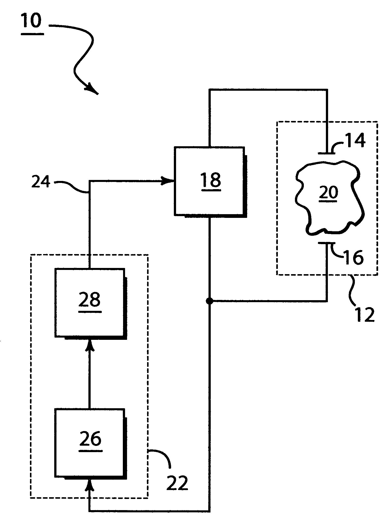
[0017] Referring to FIG. 3 there is shown a plasma processing system 10 such as a DC magnetron processing system that incorporates the principles of this invention. A plasma chamber 12 has contained therein electrodes 14 and 16. A power supply 18 supplies a voltage to the electrodes 14 and 16 in order to ignite plasma 20 in a reactive gas (not shown). Particles from the plasma are disposed to deposit a thin film on a substrate (not shown) in the chamber. To compensate for changes in the output of the power supply 18 a controller 22 automatically adjusts the control signal 24 to the power supply based upon the change of the dynamic impedance of the plasma 20. The controller is generally comprised of an analog to digital converter 26 and microprocessor 28. The A / D converter samples the output voltage and current of the power supply and the values are inputted to the microprocessor which makes a real time estimation of the dynamic impedance of the plasma and sends a control signal 24 t...


PUM

PropertyMeasurementUnit
voltageaaaaaaaaaa
dynamic impedanceaaaaaaaaaa
output voltageaaaaaaaaaa

Abstract

There is provided by this invention an apparatus and method for controlling a dc magnetron plasma processing system that automatically adjusts the control signal to the power supply based upon the dynamic impedance of the load to control the output power to the plasma. The output voltage and the output current of the power supply that supplies power to the plasma is sampled over at a sampling frequency at least four to five times higher than the switching frequency and the dynamic impedance of the plasma is calculated based upon the sampled voltage and current from the algorithm Rplasma=ΔVnΔIn
wherein ΔVn and ΔIn is the maximum difference among samples on one switching cycle. If the dynamic impedance seen is negative in nature then the control signal is compensated accordingly.

Description

BACKGROUND OF THE INVENTION [0001] 1. Field of the Invention [0002] This invention relates generally to any controller for a power supply that utilizes a compensator to shape the response of the control loop to external disturbances, and more particularly to a control means for calculating the dynamic impedance of a DC magnetron based process. [0003] 2. Brief Description of the Prior Art [0004] In plasma processing for the manufacture of thin films for integrated circuits, flat panel displays, glass coatings, etc a fast controller is required to effectively control the power delivered to a wide range of plasma processes. Controllers are designed accounting for the control to output transfer function of the power supply. The transfer function of the power supply depends on the dynamic impedance of the load. The primary function of a controller for a power supply is to achieve and maintain any commanded control signal. The controller is designed accounting for the control to output, a...

Claims


Application Information

Patent Timeline
Patent Type & Authority Applications(United States)
IPC IPC(8): H01J7/24
CPCH01J37/32027H05H1/46H01J37/3405H01J37/3299H01J7/24H01J37/32H02M3/04
Inventor ILIC, MILANSIDDABATTULA, KALYAN N.C.ROOP, GERALD C. JR.CHRISTIE, DAVID J.
Owner ADVANCED ENERGY IND INC
Why Eureka
Try Eureka