Image sensor ADC and CDS per column

a column and image sensor technology, applied in the field of solid-state imaging devices, can solve the problems of large-bus analog multiplexing, high undesired power consumption for the entire array, and large noise of analog current, and achieve the effect of reducing the available area

Inactive Publication Date: 2006-01-19
DYNAMAX IMAGING
View PDF5 Cites 40 Cited by
  • Summary
  • Abstract
  • Description
  • Claims
  • Application Information

AI Technical Summary

Benefits of technology

[0013] Accordingly, it is an object of the present invention to provide a straightforward technique for converting the video pixel signals from a solid state imaging devi

Problems solved by technology

Wide-bus analog multiplexing has significant problems due, for example, to highly capacitive loads, long settling times, voltage droop across the bus, noise cross coupling from neighboring circuits.
That surge in the analog current can inject a significant amount of noise to the highly sensitive pixel site or pixel amplifier voltage storage nodes.
Finally, if the arrayed analog buffer has to be able to drive the capacitive bus (even at moderate speeds) it will need a higher quiescent supply current in the output stage and that current gets multiplied by the number of arrayed elements to yield a very high undesired power consumption for the entire array.
A serious problem for analog arrayed circuits is that any mismatch between the devices will appear as fixed pattern noise (i

Method used


Image

  • Image sensor ADC and CDS per column
  • Image sensor ADC and CDS per column
  • Image sensor ADC and CDS per column

Examples


Embodiment Construction

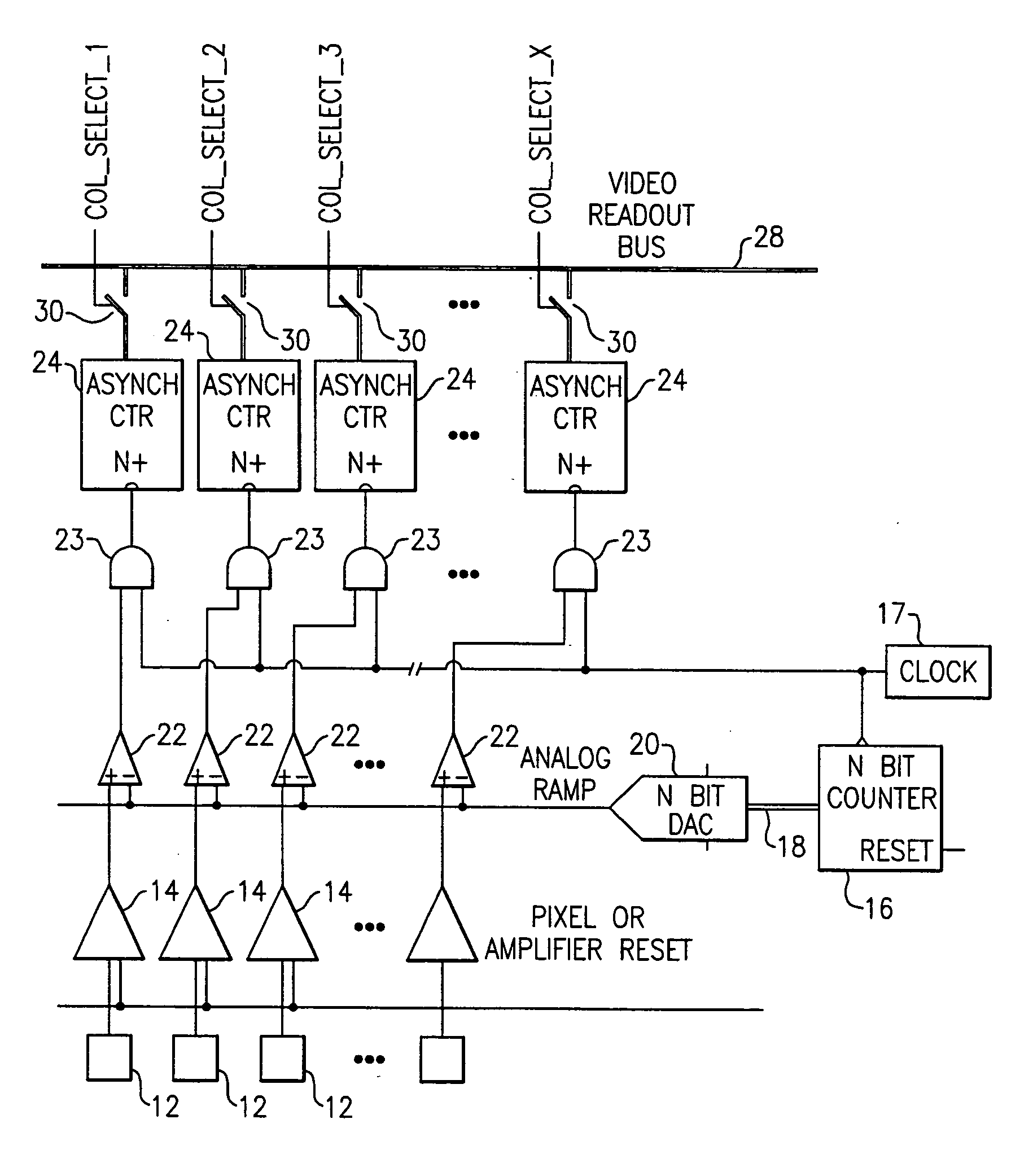
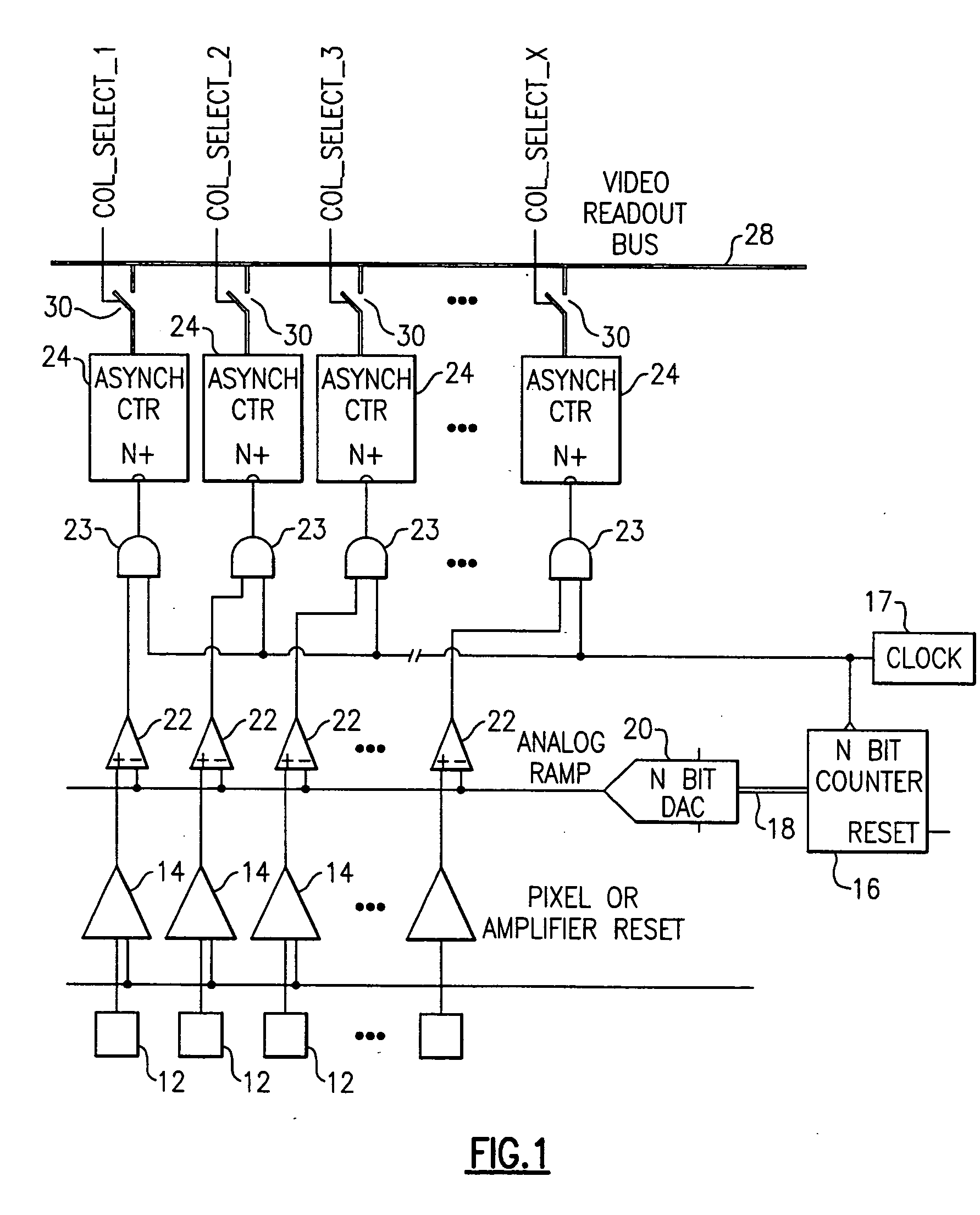
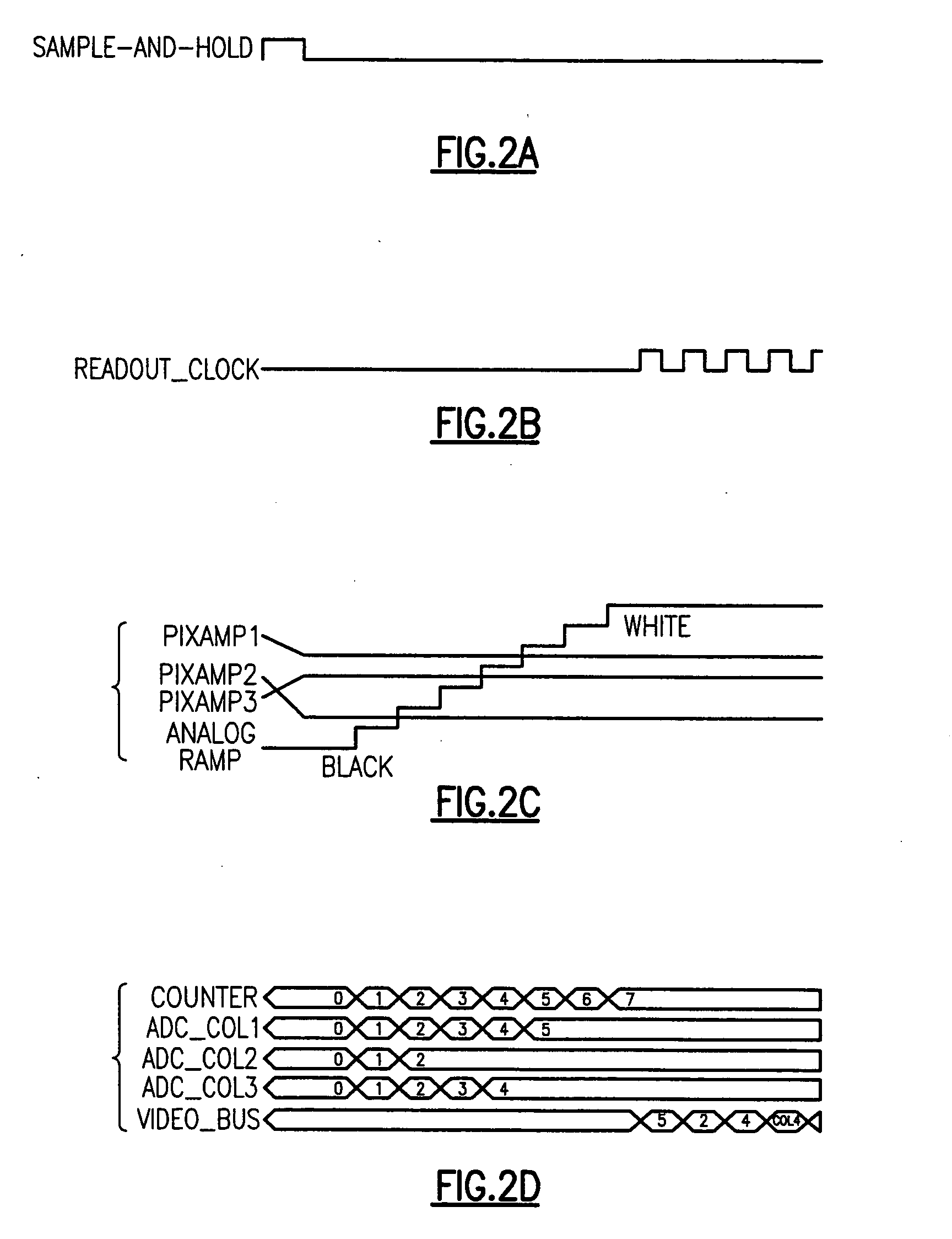
[0038] With reference to the Drawing figures, and initially to FIG. 1 thereof, an arrayed solid-state imager 10 is shown, which incorporates an N-bit ADC conversion facility that employs an N-bit counter and a DAC to generate an analog ramp.

[0039] In this imager 10, there are multiple columns, each comprising one or more pixels 12. In this case the pixel 12 represents one or multiple pixels of the same column, and each pixel 12 is connected with an input of a column amplifier 14. A pixel reset line is also connected to a reset input of each of the column amplifiers 14. An N-bit counter 16 counts up clock signals that are supplied from a clock pulse generator 17, and the counter 16 supplies a digital count value on a counter output bus 18 that supplies an input of a DAC or digital-to-analog converter element 20. For simplicity, the same clock pulse generator 17 is used for both the counter / latches 24 and the DAC 20. The user may employ different clock pulse generators to add flexibi...


PUM


Abstract

A solid state imager converts analog pixel values to digital form on an arrayed per-column basis. An N-bit counter supplies an N-bit DAC to produce an analog ramp output with a level that varies corresponding to the contents of the counter. A ripple counter or equivalent is associated with each respective column. A clock supplies clock signals to the counter elements. A comparator in each column gates the counter element when the analog ramp equals the pixel value for that column. The contents of the counters are transferred sequentially to a video output bus to produce the digital video signal. Additional black-level readout counter elements can create and store a digital value that corresponds to a dark or black video level. A subtraction element subtracts the black level value from the pixel value to reduce fixed pattern noise. An additional array of buffer counter/latches can be employed. The ripple counters can be configured as counters to capture the digital video level, and then as shift registers to clock out the video levels to an output bus. The clock pulses for the DAC counter and for the ripple counters can be at the same or different rates.

Description

[0001] This is a Continuation-in-Part of earlier copending and commonly assigned U.S. patent application Ser. No. 10 / 106,399, filed Mar. 25, 2002, now U.S. Pat. No. ______, which claims priority of Provisional Application Ser. No. 60 / 278,639, Mar. 26, 2001, now abandoned.BACKGROUND OF THE INVENTION [0002] This invention relates to solid state imaging devices, and is more specifically directed to an imager that converts analog pixel values to corresponding digital values on an arrayed basis, with significantly reduced circuitry. The invention is also concerned with compensation of errors that may be present in conversion, as well as correction for offset errors attributable to the pixel photo sensor areas or to the pixel amplifiers. DESCRIPTION OF THE PRIOR ART [0003] The term “array” used herein refers to any kind of repeatable circuit and covers for instance a circuit per column or a circuit per row in an area (two-dimensional) sensor, or an entire line in a linear sensor (theoreti...

Claims


Application Information

Patent Timeline
IPC IPC(8): H04N3/14H03M1/12H03M1/56H04N5/335
CPCH03M1/1019H03M1/123H03M1/1235H03M1/56H04N5/378H04N5/3742H04N5/37455H04N5/3765H04N5/335H04N25/00H04N25/767H04N25/772H04N25/745H04N25/75
Inventor ZARNOWSKI, JEFFREY J.KARIA, KETAN V.POONNEN, THOMAS
Owner DYNAMAX IMAGING
Why Eureka
Try Eureka