Dc converter

a direct-current converter and converter technology, applied in the direction of electric variable regulation, process and machine control, instruments, etc., can solve the problems of increasing switching noise and very unstable operation of direct-current converters, and achieve the effect of improving the unstableness of operations, eliminating the influence of delay, and increasing switching nois

Inactive Publication Date: 2006-01-19
SANKEN ELECTRIC CO LTD
View PDF3 Cites 22 Cited by
  • Summary
  • Abstract
  • Description
  • Claims
  • Application Information

AI Technical Summary

Benefits of technology

[0015] Moreover, when there is a delay from the detection of the bottom to the switch-on of the main switch Q1, the switch-on of the main switch Q1 is delayed from the bottom. Accordingly, it has been necessary to configure such a circuit which reduces the delay from the detection of the bottom to the switch-on of the main switch Q1. Therefore, it has been necessary to switch on the main switch Q1 at high speed, leading to a defect that switching noise is increased, and the like.
[0016] It is an object of the present invention to provide a direct-current converter which improves the unstableness of the operations owing to the error of the bottom detection circuit and the fluctuations of the detection point which are caused by the disturbance, is capable of eliminating an influence of the delay from the detection of the bottom to the switch-on of the main switch, and capable of reducing the switching noise.

Problems solved by technology

Accordingly, the operations of the direct-current converter become very unstable.
Therefore, it has been necessary to switch on the main switch Q1 at high speed, leading to a defect that switching noise is increased, and the like.

Method used


Image

  • Dc converter
  • Dc converter
  • Dc converter

Examples


first embodiment

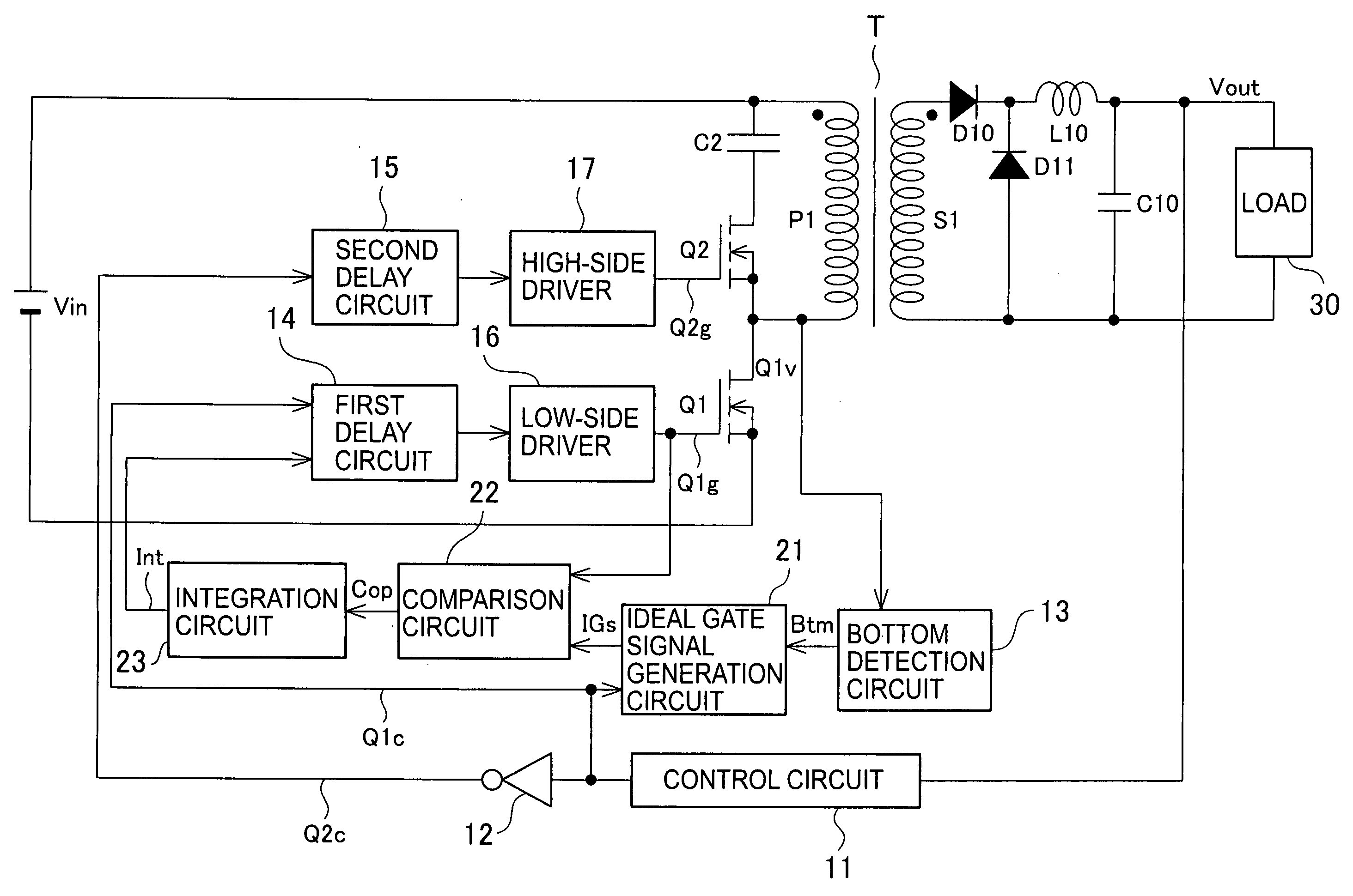
[0032]FIG. 3 is a circuitry diagram of a direct-current converter according to a first embodiment. In the direct-current converter shown in FIG. 3, a main switch Q1 and an auxiliary switch Q2 are configured to be alternately switched on / off by PWM control of a control circuit 11. Based on an output voltage of a load 30, the control circuit 11 generates a control signal formed of a pulse for controlling ON / OFF of the main switch Q1, and controls a duty ratio of the control signal so that the output voltage becomes a predetermined voltage.

[0033] Moreover, the direct-current converter includes an inverter 12, a bottom detection circuit 13, a first delay circuit 14, a second delay circuit 15, a low-side driver 16, a high-side driver 17, an ideal gate signal generation circuit 21, a comparison circuit 22, and an integration circuit 23.

[0034] The inverter 12 inverts a Q1 control signal Q1c for the main switch Q1 from the control circuit 11, and outputs the inverted Q2 control signal Q2c...

second embodiment

[0050]FIG. 6 is a circuitry diagram of a direct-current converter according to a second embodiment. The direct-current converter according to the second embodiment, which is shown in FIG. 6, provides a specific circuit example of the direct-current converter according to the first embodiment.

[0051] In the bottom detection circuit 13 shown in FIG. 6, a cathode of a diode D1, one end of a resistor R1 and one end of a resistor R10 are connected to a base of a transistor Q3, and an emitter of the transistor Q3 is connected to an anode of the diode D1, and grounded. One end of a resistor R2 is connected to a collector of the transistor Q3, and the other end of the resistor R1 and the other end of the resistor R2 are connected to a power supply Vcc. The other end of the resistor R10 is connected to a drain of the main switch Q1 through a capacitor C1.

[0052] The ideal gate signal generation circuit 21 includes an inverter 211, an inverter 212, and a D-type flip-flop (DFF) 213. The invert...

third embodiment

[0071]FIG. 8 is a circuitry diagram of a direct-current converter according to a third embodiment. The direct-current converter according to the third embodiment, which is shown in FIG. 8, is one which obtains a direct-current output by switching on / off the main switch. The direct-current converter according to the third embodiment is characterized in that the auxiliary switch Q2, the inverter 12, the second delay circuit 15, the high-side driver 17, the capacitor C2, the diode D11 and the reactor L10 are deleted from the configuration of the direct-current converter according to the first embodiment, which is shown in FIG. 3. Moreover, the primary winding P1 and secondary winding S1 of the transformer T are wound in phases reverse to each other.

[0072] Other configurations shown in FIG. 8 are the same as the configurations of the constituent portions shown in FIG. 3. The same reference numerals are assigned to the same portions, and description thereof is omitted.

[0073] Next, oper...


PUM


Abstract

What is provided is a direct-current converter which improves unstableness of operations owing to an error of a bottom detection circuit and fluctuations of a detection point which are caused by disturbance. The direct-current converter includes a bottom detection circuit 13 which detects a minimum voltage of a main switch Q1 after an auxiliary switch Q2 is switched off, an ideal gate signal generation circuit 21 which generates an ideal gate signal for switching on the main switch Q1 at a time of the minimum voltage of the main switch Q1 based on an output of the bottom detection circuit 13, a comparison circuit 22 which calculates an error output between the ideal gate signal generated by the ideal gate signal generation circuit 21 and an actual gate signal which switches on the main switch Q1, and a first delay circuit 14 which controls a delay of an ON time of the main switch Q1 by the actual gate signal based on the error output of the comparison circuit 22, thereby performing control to make the actual gate signal approach the ideal gate signal.

Description

TECHNICAL FIELD [0001] The present invention relates to a direct-current converter which is high-efficiency and low-noise. BACKGROUND ART [0002]FIG. 1 shows an example of a conventional direct-current converter (Japanese Patent Laid-Open Publication No. 2000-92829). The direct-current converter shown in FIG. 1 has a system called “active clamp”. To a direct-current power supply Vin, a main switch Q1 formed of a MOSFET (hereinafter, referred to as an FET) and the like is connected through a primary winding P1 (winding number: n1) of a transformer T. To both ends of the primary winding P1, a series circuit composed of an auxiliary switch Q2 formed of a MOSFET (hereinafter, referred to as an FET) and the like and composed of a snubber capacitor C2 is connected. The main switch Q1 and the auxiliary switch Q2 are configured to be alternately switched on / off by PWM control of a control circuit 111. [0003] Moreover, the primary winding P1 of the transformer T and a secondary winding S1 of ...

Claims


Application Information

Patent Timeline
Patent Type & Authority Applications(United States)
IPC IPC(8): H02M3/335H02M1/34H02M3/28
CPCH02M1/34H02M3/33507Y02B70/1491H02M2001/342H02M3/33569Y02B70/10H02M1/342H02M3/33571H02M3/01
Inventor ASO, SHINJI
Owner SANKEN ELECTRIC CO LTD
Why Eureka
Try Eureka