Power supply device and air conditioner using the same

a power supply device and air conditioner technology, applied in the direction of converting intermediate power to dc, climate sustainability, power electronics conversion efficiency, etc., can solve the problems of not being able to effectively use a power, the power factor is worsened, and the reactive power is large, so as to reduce the noise of switching and loss, reduce the harmonic distortion, and reduce the effect of switching noise and loss

Inactive Publication Date: 2006-04-11
PANASONIC CORP
View PDF24 Cites 29 Cited by
  • Summary
  • Abstract
  • Description
  • Claims
  • Application Information

AI Technical Summary

Benefits of technology

[0025]In the power supply device according to the present invention, a wide conduction period can be obtained to restrict a harmonic distortion, and realize a power supply device which can reduce a switching noise and a loss by a simple construction and control. Further the power supply device according to the present invention provides a low-loss air conditioner which has high power factor and can restrict a harmonic distortion.
[0026]An air conditioner with high efficiency, low harmonic and low loss also can be provided by applying thereto the power supply device according to the present invention.

Problems solved by technology

However, in the capacity input type rectifier circuit, a conduction period of an input current becomes narrow, and then, a power factor is worsened, and further, a reactive power is much.
For this reason, it is not possible to effectively use a power, and the input current contains much harmonic distortions, as a result, there is a problem of fault to equipment connected to the identical power supply device.
However, in the above power supply device shown in FIG. 31A, its improvement effect is low although the power supply device can improve a power factor with a simple construction and a sufficient power factor can not be obtained.
Since a reactor value must be made large in order to obtain high power factor with the circuit construction, it causes a problem that components would be made into a large size and a loss would simultaneously increase.
Even though the above power supply device shown in FIG. 32A can form the input current into a shape of sine wave and control a power factor to approximately 1, the power supply device has the following problems.
More specifically, the control becomes complicate, and a loss in the switching element 107 is increased due to high frequency switching accompanying with waveform shaping, and further, a switching noise increases.
This causes a cost increase, an increase of loss in the filter circuit, and finally efficiency deterioration as a whole.
However, the control becomes complicate, because both of a delay time and a pulse width must be controlled.
Further, in the case where the above power supply device is applied to an air conditioner or the like, the reactor is made into a large size in inputting 200V, and then, a loss is increased in the large-sized reactor.
Further, since a voltage applied to switching means becomes high, a component having a high withstand voltage is required.
As a result, the component is made into a large size, and a switching loss becomes great in the switching element 107.
This power supply device however has the following problems.
More specifically, as shown in FIG. 34B, when an output voltage increases, a voltage boost ratio becomes higher, and the power supply device is close to the voltage double rectifier circuit Consequently a sufficient power factor can not be obtained.
It is impossible to obtain an output voltage more than a voltage obtained by the voltage doubler rectification.

Method used


Image

  • Power supply device and air conditioner using the same
  • Power supply device and air conditioner using the same
  • Power supply device and air conditioner using the same

Examples


first embodiment

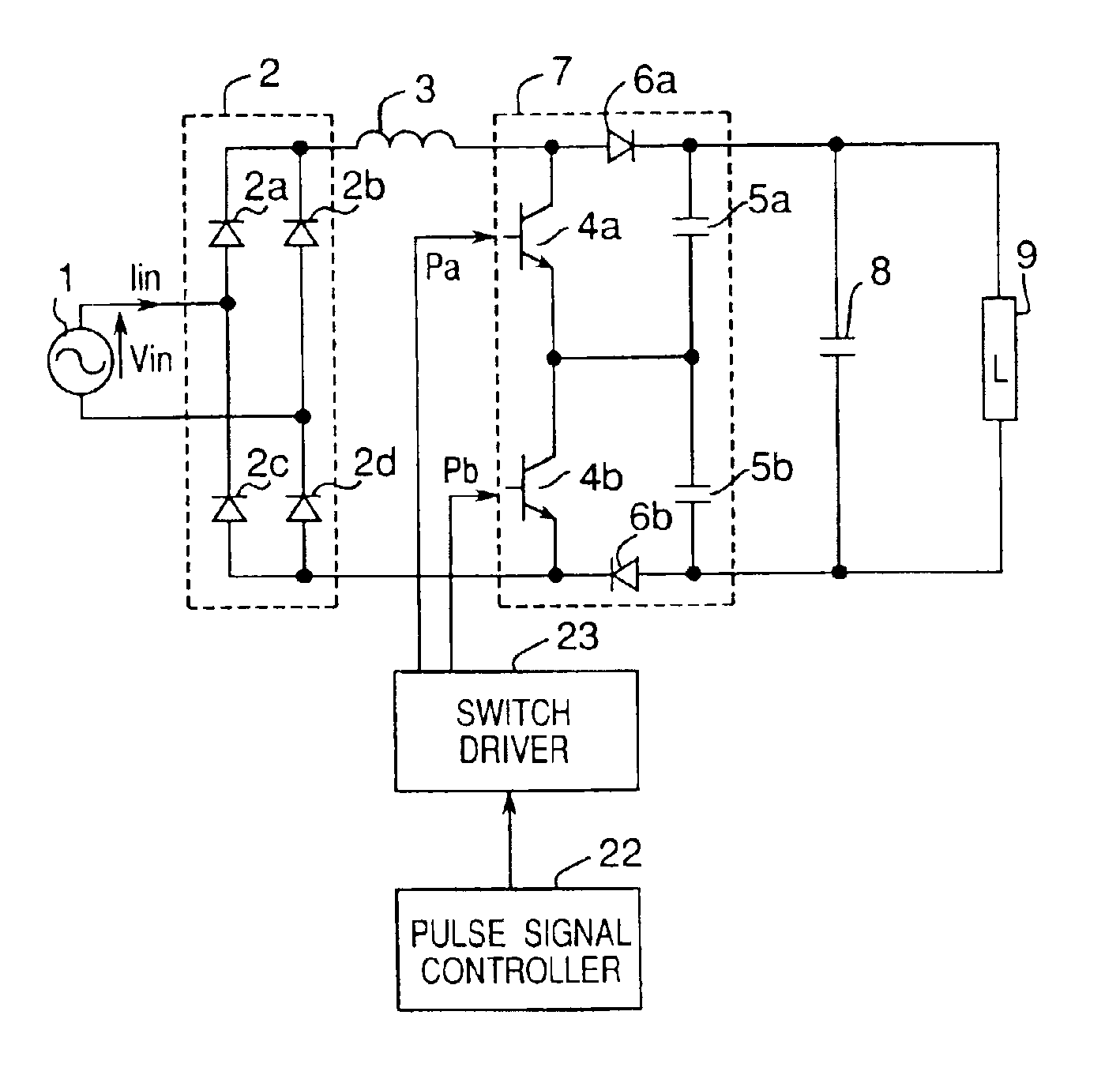
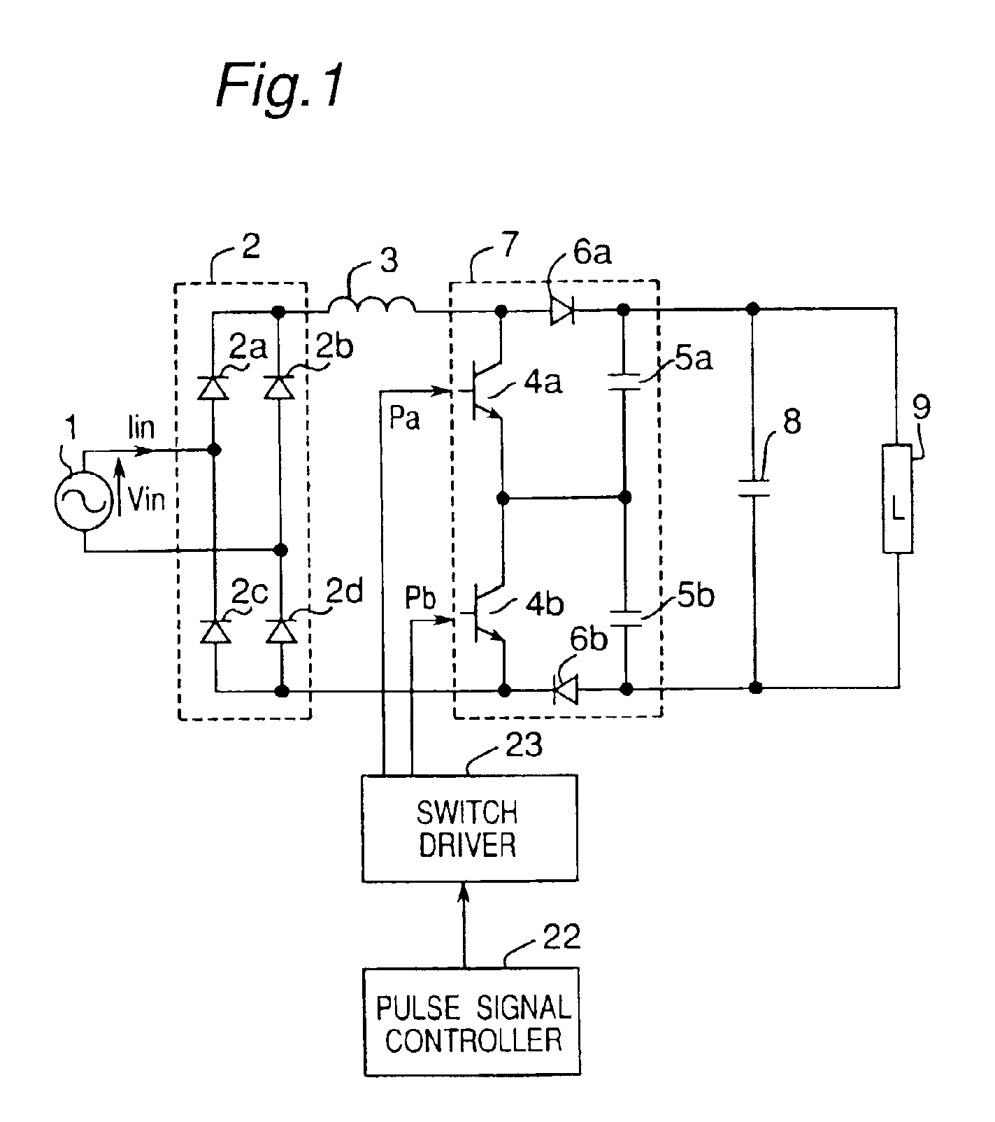
[0062]FIG. 1 is a circuit diagram showing a construction of a power supply device according to one embodiment of the present invention. In FIG. 1, The power supply device comprises a rectifier circuit 2 for rectifying an AC voltage from an AC power supply 1 to output a rectified ripple voltage, a reactor 3 for improving a power factor, a power factor correction circuit 7 and a smoothing capacitor 8 for smoothing an output voltage of the power factor correction circuit 7 to supply the voltage to a load 9. The rectifier circuit 2 is composed of a plurality of rectifier elements 2a, 2b, 2c and 2d. The power factor correction circuit 7 is composed of two switching elements 4a and 4b connected in series, and two capacitors 5a and 5b connected in series, and two reverse blocking rectifier elements 6a and 6b. An intermediate point of the serial connection of two switching elements 4a and 4b is connected with an intermediate point of the serial connection of two capacitors 5a and 5b. The sw...

second embodiment

[0069]FIG. 3 is a circuit diagram showing a construction of a power supply device according to another embodiment of the present invention. As shown in FIG. 3, the power supply device further includes a zero cross detecting circuit 21 which detects a zero cross point of the AC power supply 1, and outputs a zero crass detection signal, in addition to the circuit construction shown in FIG. 1. FIG. 4 shows a construction of the power supply device including the zero cross detecting circuit 21 shown in detail. The zero cross detecting circuit 21 alternately detects a zero cross point of the AC power supply 1 for each half period with the use of resistors 62a, 62b, 63a and 63b and Photo-couplers 61a and 61b. The pulse signal controller 22 receives a zero cross detection signal from the zero cross detecting circuit 21, and then, generates and outputs a pulse signal for driving the switching elements 4a and 4b. This pulse signal controller 22 a composed of a general logic circuit or a micr...

third embodiment

[0079]FIG. 6 is a view showing each waveform (hereinafter, referred to as “principal waveform) of a power supply voltage, an input current, and both ends voltage of each capacitor, and a waveform of a pulse in a power supply device according to still another embodiment of the present invention. FIG. 7 is a view showing a change of a current flowing path in the power supply device. A positive half period of a power supply voltage a divided into five periods, and then, an operation of each period will be described below in detail with reference to FIGS. 3, 6 and 7. In the following description, “Va” or “Vb” shows a voltage across capacitors 5a or 5b respectively, and “Vdc” shows a voltage across the smoothing capacitor 8.

[0080]Period {circle around (1)}: The pulse signal controller 22 outputs a pulse signal for taming on either of the switching elements 4a and 4b for a predetermined time in synchronous with the zero cross point of the voltage Vin of the AC power supply 1. In the examp...


PUM


Abstract

This invention provides a power supply device capable of widening a conduction period of an input current by a simple control to improve a power factor, and reducing a harmonic distortion of the input current The power supply device comprises a rectifier circuit, a reactor, a power factor correction circuit having switching elements, capacitors and a reverse-current blocking rectifier elements, a smoothing capacitor for smoothing an output voltage of the power factor correction circuit to obtain a DC voltage, a pulse signal controller generating and outputting a pulse signal for turning on and off the switching elements, and a driver for receiving the pulse signal to drive a switching elements of the power factor correction circuit.

Description

BACKGROUND OF THE INVENTION[0001]1. Field of the Invention[0002]The present invention relates to a power supply device which converts an alternating current into a DC, and reduces a harmonic distortion of an input current so as to improve a power factor.[0003]2. Description of the Related Art[0004]Conventionally, a capacitor input type rectifier circuit has been used as an AC-to-DC converter circuit in various fields. The capacitor input type rectifier circuit inputs an AC voltage to a diode rectifier circuit so as to obtain a ripple voltage output, and smoothens the ripple voltage output by a capacitor so as to obtain a DC voltage. However, in the capacity input type rectifier circuit, a conduction period of an input current becomes narrow, and then, a power factor is worsened, and further, a reactive power is much. For this reason, it is not possible to effectively use a power, and the input current contains much harmonic distortions, as a result, there is a problem of fault to eq...

Claims


Application Information

Patent Timeline
Patent Type & Authority Patents(United States)
IPC IPC(8): H02M1/12H02M5/42H02M1/00H02M1/42
CPCH02M1/4208Y02B70/10
Inventor OKUI, HIROSHIOGAWA, MASANORI
Owner PANASONIC CORP
Why Eureka
Try Eureka