
Method and apparatus for adding auxiliary channels in an existing transmission system

a technology of auxiliary channels and transmission systems, applied in the field of communication systems, can solve the problems of prohibitive cost of replacing all existing receivers in the system, difficulty in adding such auxiliary channels, and reducing the rate of primary data, and achieve the effect of small nois

Inactive Publication Date: 2006-01-19
LUCENT TECH INC
View PDF6 Cites 19 Cited by
  • Summary
  • Abstract
  • Description
  • Claims
  • Application Information

AI Technical Summary

Benefits of technology

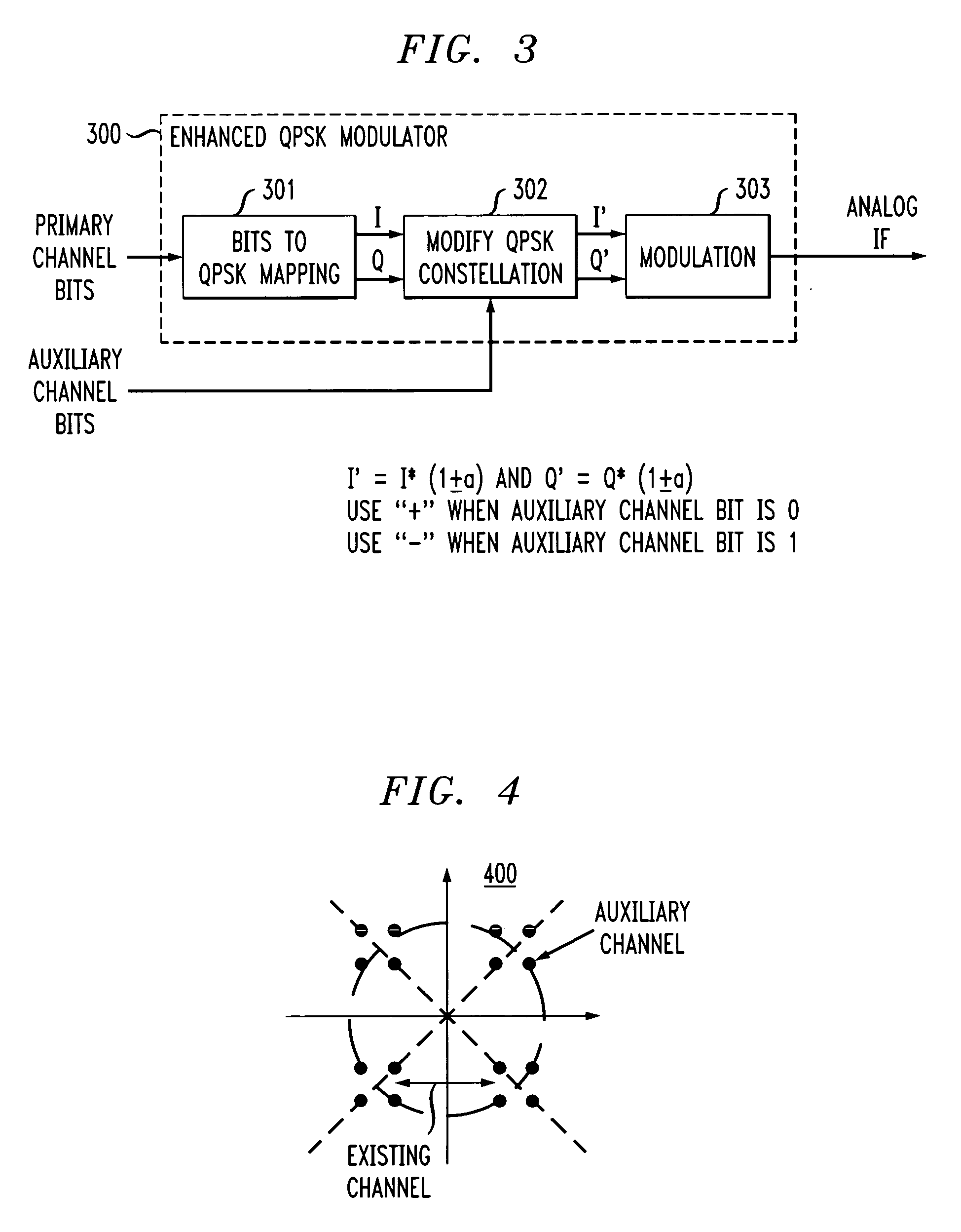
[0009] In a receiver that is deployed before the enhanced QPSK system is introduced, the amplitude variation +/−a represents a small noise in the transmission system. Such a receiver will demodulate the primary channel only, regar

Problems solved by technology

However, there are difficulties in adding such an auxiliary channel.
One difficulty in adding an auxiliary channel is the fact that the existing system, i.e., the primary system, is designed to transmit a specific data rate, and the addition of the auxiliary channel would require a reduction in this primary data rate, which is undesirable.
Another problem is that the new system must or should be backward compatible with existing receivers so that the existing receivers can at least receive the primary channel data.
Otherwise, the cost of replacing all the existing receivers in the system could be prohibitive.

Method used


Image

  • Method and apparatus for adding auxiliary channels in an existing transmission system
  • Method and apparatus for adding auxiliary channels in an existing transmission system
  • Method and apparatus for adding auxiliary channels in an existing transmission system

Examples


Embodiment Construction

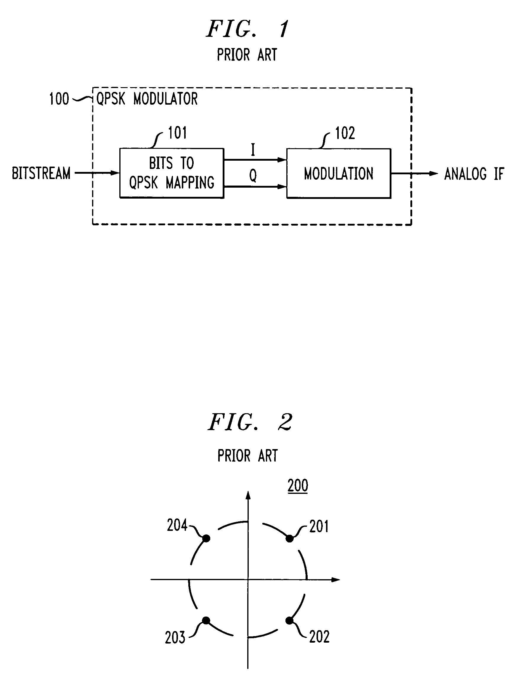
[0016]FIG. 1 shows, in simplified block diagram form, details of a prior known QPSK modulator 100. Specifically, shown are bits to QPSK Mapping Unit 101 and Modulation Unit 102.

[0017] In QPSK modulation, a cosine carrier is typically varied in phase while maintaining a constant amplitude and frequency. The term “quadrature” implies that there are four possible phases (4-PSK), which the carrier can have at a given time, as shown in FIG. 2 on the characteristic constellation. The four phases are labeled 201, 204, 203 and 202 corresponding to one of 45, 135, 225 and 315 degrees, respectively.

[0018] In QPSK, information is conveyed through phase variations. This is realized in Bits to QPSK Mapping Unit 101 where the input digital bitstream is mapped into the in-phase (I) and quadrature-phase (Q) components of the QPSK signal (the primary QPSK channel). The I component is the real part and the Q component is the imaginary part of the QPSK symbols. Specifically, in each time period, the...


PUM


Abstract

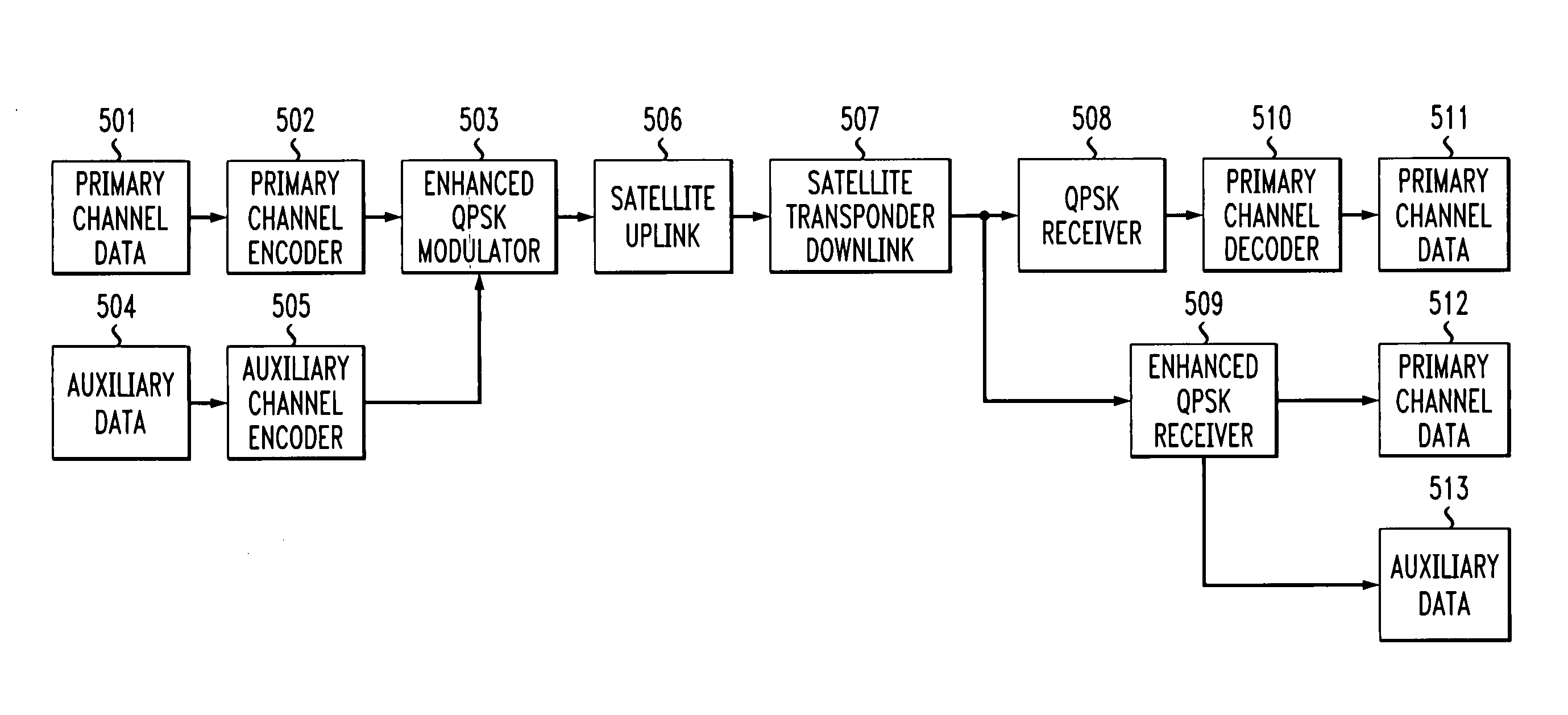
A unique new modulation scheme is employed to add the auxiliary channel. This is realized, in one embodiment of the invention, in a quadrature phase shift keying (QPSK) transmission system, by utilizing a “large” phase variation component to modulate the primary channel and a relatively “small” amplitude variation component to modulate the new auxiliary channel. There are a number of known transmission schemes in which applicant's unique auxiliary channel modulation scheme can be used to realize his unique invention. One example for such a transmission system an enhanced QPSK transmission system. The primary channel, or the original transmission system, uses PQSK where every two bits of data is mapped to a symbol I+j Q, where j is the imaginary unity. In the enhanced QPSK transmission system, every two bits from the primary channel data, and every two bits from the auxiliary channel data are mapped to the symbol I(1+ / −a)+j Q(1+ / −a). The mapping between the two bits from the primary channel data and I, Q is the same as in the prior QPSK system. However, in the enhanced QPSK system, the auxiliary channel data is carried in the system by the variation + / −a. The sign “+ / −” depends on the polarity of the auxiliary channel bits. The amplitude “a” can be adjusted to adjust the data rate of the auxiliary channel and the interference to the primary channel.

Description

RELATED APPLICATION [0001] U.S. patent application Ser. No. (H. Jiang 16) was filed concurrently herewith. TECHNICAL FIELD [0002] This invention relates to communication systems and, more particularly, to transmitting auxiliary channels in an existing system. BACKGROUND OF THE INVENTION [0003] Many known digital transmission systems, especially those that utilize satellites, employ quadrature phase shift keying (QPSK) as the modulation format for transmitting digital data. Examples of such systems are digital satellite television, digital satellite radio and the like. Such digital transmission systems usually include a variety of transmission equipment, for example, a data source generator, a source encoder, a channel encoder and a modulator. The modulator, in well known fashion, modulates the encoded source data in a particular format, in this example QPSK, for transmission over a transmission medium to remote receivers. Typically, at the receivers an antenna receives the modulated...

Claims


Application Information

Patent Timeline
IPC IPC(8): H04J11/00
CPCH04B7/18517H04L27/3488H04L5/12
Inventor JIANG, HONG
Owner LUCENT TECH INC
Learn More