Electrical heater, heating heat exchanger and vehicle air conditioner

Inactive Publication Date: 2006-01-19
DENSO CORP
View PDF6 Cites 14 Cited by
  • Summary
  • Abstract
  • Description
  • Claims
  • Application Information

AI Technical Summary

Benefits of technology

[0007] In view of the above-described problems, it is an object of the present invention to provide an electrical heater which effectively improves heat radiating performance while having a simple structure.
[0008] According to an aspect of the present invention, an electrical heater includes a plurality of heating body plates arranged in parallel with each other to define an air passage through which air flows between adjacent two thereof, a positive electrode member joined to one end side of each heating body plate, and a negative electrode member joined to the other end side of each heating body plate. In the electrical heater, the heating body plates are arranged to directly heat air passing through the air passage when electrical power is supplied to the heating body plates through the electrode members. In the present invention, because the heating body plates directly define the air passage through which air flows to directly heat air flowing through the air passage, heat radiating performance of the electrical heater can be improved while the electrical heater has a simple structure. Each of the heating body plates can be formed to have a flat shape or a wave shape. When the heating body plates are arranged in such a manner that the wave shape is bent in a direction perpendicular to an air flow direction in the air passage, heat transmitting performance of air can be effectively improved in the electrical heater. Alternatively, each of the heating body plates has protrusion portions protruding from at least one of face and back surfaces of each heating body plate to the air passage.
[0010] According to another aspect of the present invention, an electrical heater includes a single heating body plate bent in a spiral shape by interposing an air gap portion at a predetermined interval so as to define air passages by using the air gap portion, a positive electrode member joined to one end side of the heating body plate, and a negative electrode member joined to the other end side of the heating body plate. In addition, the heating body plate is disposed to directly heat air passing through the air passages when electrical power is supplied to the heating body plate through the electrode members. In this case, the structure of the electrical heater can be made simple while the radiating performance of the electrical heater can be improved. Even in this case, the positive electrode member can be arranged at one end side of the heating body plate in an air flow direction of the air passages, and the negative electrode member can be arranged at the other end side of the heating body plate in the air flow direction. In this case, the resistance value of the heating body plate can be set at a suitable value without relating to the length of the spiral shape in the spiral direction. Even in this case, the heating body plate can be molded integrally with the positive electrode member and the negative electrode member.
[0011] According to a further another aspect of the present invention, an electrical heater includes a block-shaped heating body having a plurality of ventilation hole through which air flows, a positive electrode member joined to one end side of the block-shaped heating body, and a negative electrode member joined to the other end side of the block-shaped heating body. In the electrical heater, the heating body is disposed to directly heat air passing through the ventilation holes when electrical power is supplied to the heating body through the electrode members. Even in this case, the electrical heater can effectively heat air.
[0014] According to a further another aspect of the present invention, a heating heat exchanger includes a plurality of heat transfer plates arranged in parallel with each other at a predetermined interval to define an air passage through which air flows between adjacent two thereof, a plurality of heating body plates each of which is integrated with a corresponding one of the heat transfer plates. Each of the heat transfer plates has a plurality of fluid passages through which a fluid flows to heat air passing through the air passage, and the heating body plates generate heat when electrical power is supplied thereto. In the heating heat exchanger, the heat transfer plates and the heating body plates are arranged to heat air passing through the air passages by using the hot water and the generated heat as heating sources. Accordingly even when the temperature of the fluid is low, air passing through the heating heat exchanger can be effectively heated by the electrical heater.

Problems solved by technology

Because the PTC heating body is manufactured by ceramic, the freedom degree of the selection of a molding shape is low.
As this result, fin efficiency is reduced and heat radiating performance becomes worse.
Therefore, the structure of this heater becomes complicated.

Method used


Image

  • Electrical heater, heating heat exchanger and vehicle air conditioner
  • Electrical heater, heating heat exchanger and vehicle air conditioner
  • Electrical heater, heating heat exchanger and vehicle air conditioner

Examples


first embodiment

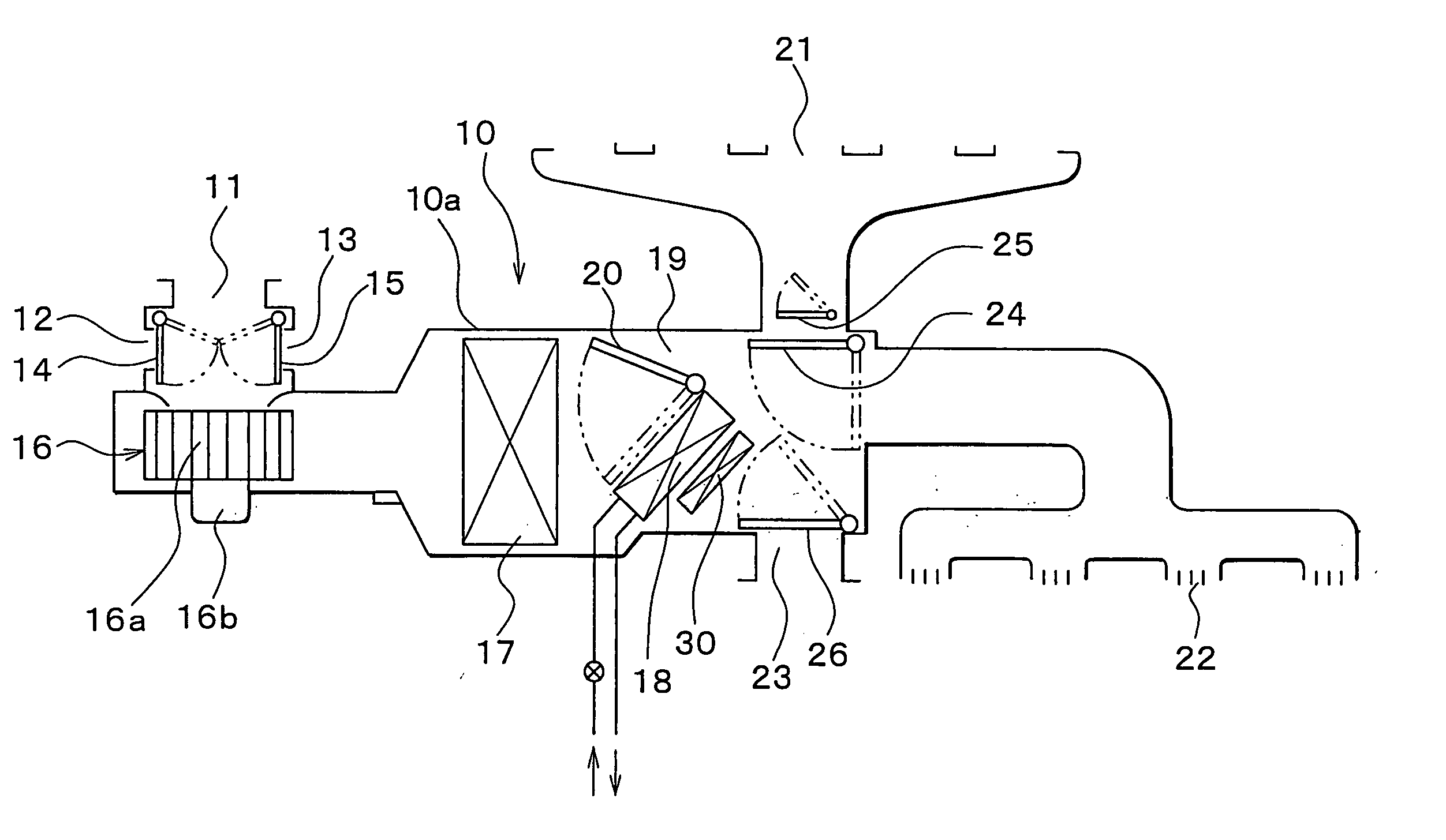
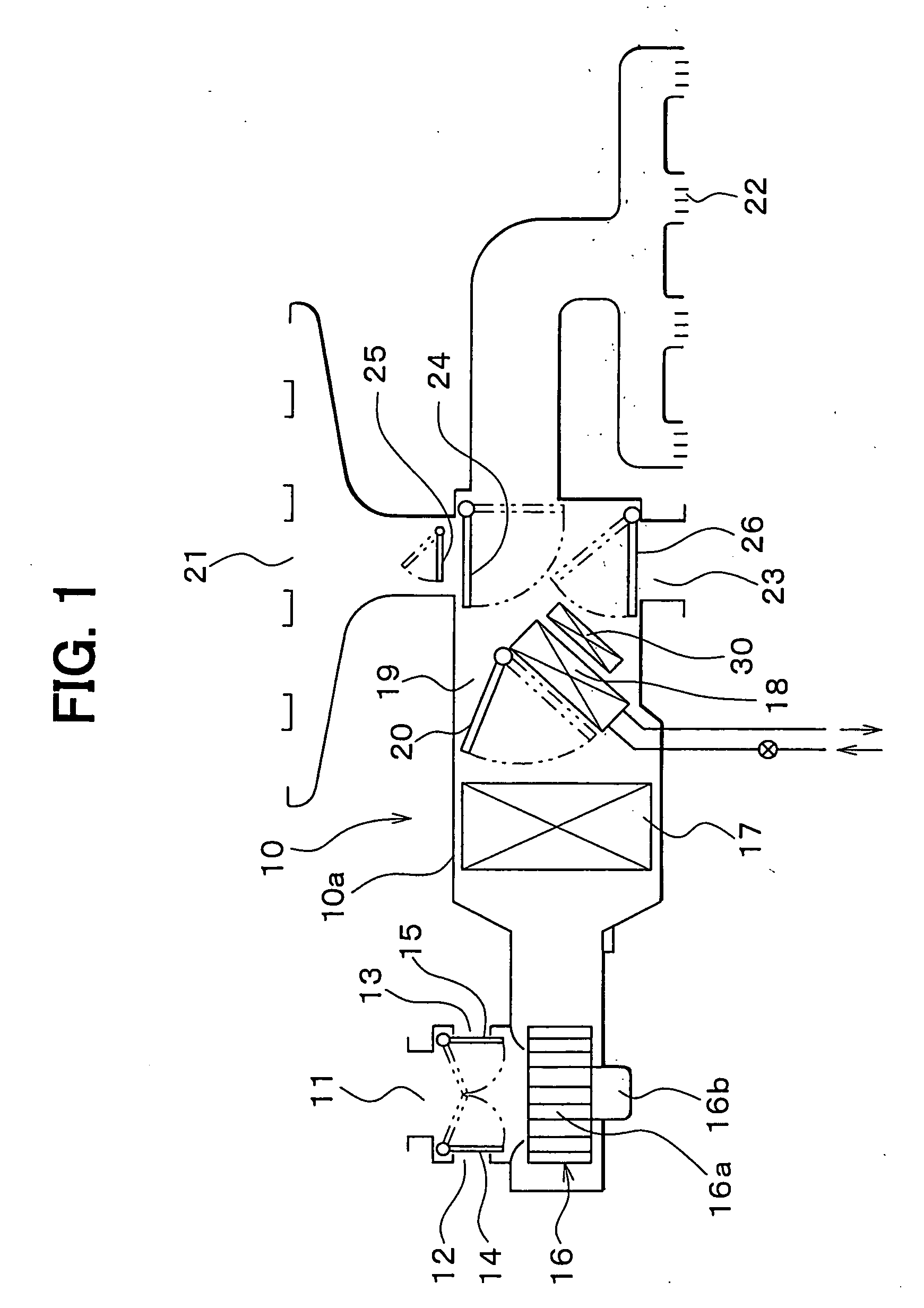
[0031] The first embodiment of the present invention will be now described with reference to FIGS. 1 and 2. An air conditioner for a vehicle using an electrical heater of the first embodiment will first be described. FIG. 1 shows the schematic structure of an interior air conditioning unit portion 10 of the air conditioner for a vehicle. This interior air conditioning unit portion 10 is normally mounted to the inside of an unillustrated vehicle dashboard (instrument board) located in the forefront portion of a vehicle passenger compartment. An outside air introducing inlet 11, inside air introducing inlets 12, 13, and inside and outside air switching doors 14, 15 for opening and closing these introducing inlets 11, 12, 13 are arranged in the most upstream portion of an air flow of this interior air conditioning unit portion 10.

[0032] Outside air (i.e., air outside the vehicle passenger compartment) or inside air (i.e., air inside the vehicle passenger compartment) introduced from t...

second embodiment

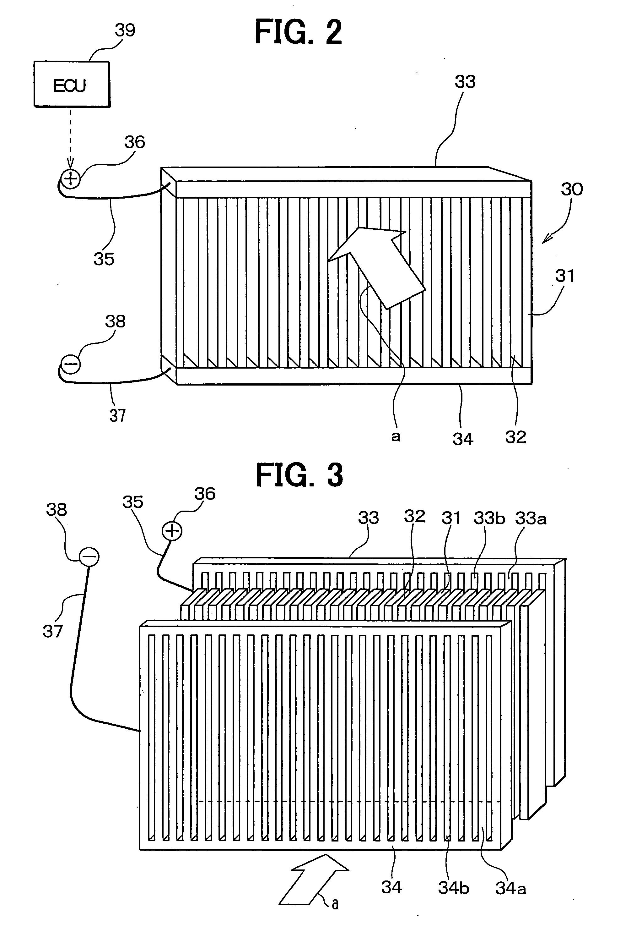
[0051] The second embodiment of the present invention will be now described with reference to FIG. 3.

[0052] In the above-described first embodiment, the electrode members 33, 34 are arranged in both the end portions of each of the plural heating body plates 31 in their longitudinal direction (vertical direction of FIG. 1). That is, the electrode members 33, 34 extend at both the end portions of each heating body plate 31 to be parallel to the air flow direction “a”. However, in the second embodiment, as shown in FIG. 3, electrode members 33, 34 are arranged in two end portions of each heating body plate 31 in a short side direction (lateral direction). That is, the electrode members 33, 34 are arranged at the upstream and downstream end portions of the heating body plates 31 in the air flow direction “a”.

[0053] Therefore, in the second embodiment, joining portions 33a, 34a of a short strip shape bonded to the upstream and downstream end portions of the respective heating body plat...

third embodiment

[0054] The third embodiment of the present invention will be now described with reference to FIGS. 4A and 4B.

[0055] In the above-described first and second embodiments, the heating body plate 31 and the electrode members 33, 34 are respectively molded in advance as separate bodies, and the end portions of the plural heating body plates 31 arranged in parallel with each other are integrally joined to the electrode members 33, 34 of the plate shape. However, in the third embodiment, as shown in FIGS. 4A and 4B, auxiliary electrode members 330, 340 constructed with electrically conductive bodies of copper, etc. are integrally molded in the end portions of the respective heating body plates 31.

[0056] Specifically, in FIG. 4A, the auxiliary electrode members 330, 340 constructed with the electrically conductive bodies of copper, etc. are integrally molded with both the end portions of the respective heating body plates 31 in their longitudinal direction (vertical direction of FIG. 1). ...


PUM


Abstract

An electrical heater includes plural heating body plates arranged in parallel with each other to define an air passage between adjacent two thereof, a positive electrode member joined to one end side of each heating body plate, and a negative electrode member joined to the other end side of each heating body plate. In the electrical heater, the heating body plates are arranged to directly heat air passing through the air passage when electrical power is supplied to the heating body plates through the electrode members. Accordingly, the electrical heater can effectively heat air with a simple structure.

Description

CROSS-REFERENCE TO RELATED APPLICATIONS [0001] This application is a divisional of U.S. patent application Ser. No. 10 / 863,801 filed on Jun. 8, 2004. This application claims the benefit of JP 2003-165110, filed Jun. 10, 2003. The disclosure of the above application is incorporated herein by reference.FIELD OF THE INVENTION [0002] The present invention relates to an electrical heater, a heating heat exchanger including a heater core integrated with the electrical heater, and an air conditioner for a vehicle using the electrical heater or the heating heat exchanger. BACKGROUND OF THE INVENTION [0003] Various kinds of electrical heaters having an electric heating body for generating heat by flowing an electric current through this electric heating body are conventionally proposed (e.g., JP-B2-3274234). In this prior art, a PTC heating body manufactured by ceramic and suddenly increased in an electric resistance value at a predetermined temperature is used as the electric heating body, ...

Claims


Application Information

Patent Timeline
IPC IPC(8): F24H1/10H05B3/78B60H1/03H05B3/14B60H1/22F24H3/04F28F9/00
CPCB60H1/2225F24H3/0405F24H9/1872F24H3/0435F24H3/0429
Inventor ITO, HITOSHITORIGOE, EIICHINAKAMURA, MITSUGU
Owner DENSO CORP
Why Eureka
Try Eureka