Heat dissipation device and power module
- Summary
- Abstract
- Description
- Claims
- Application Information
AI Technical Summary
Benefits of technology
Problems solved by technology
Method used
Image
Examples
embodiment 1
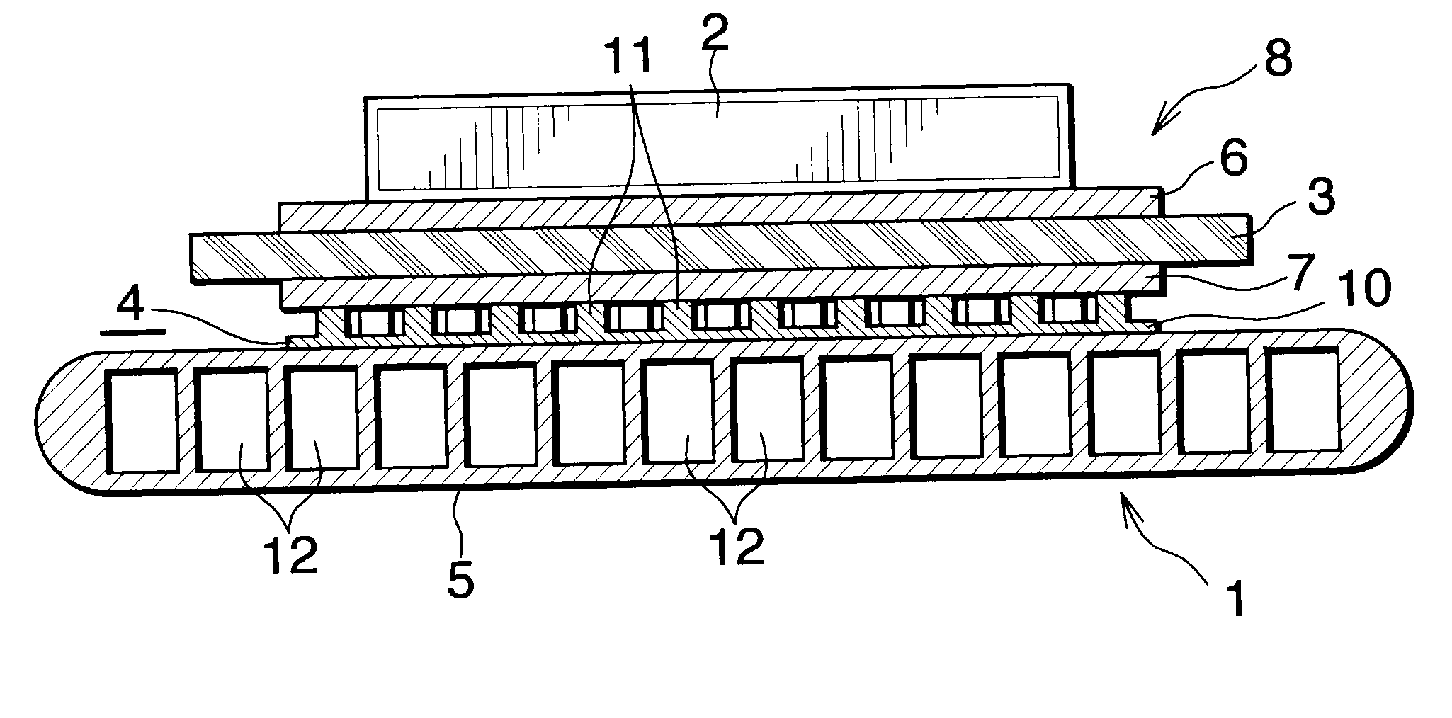
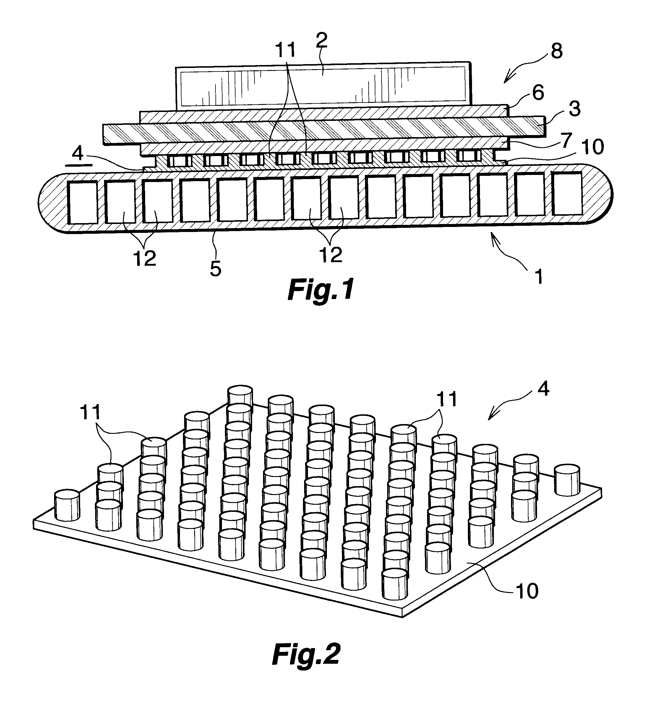
[0034]The present embodiment is shown in FIGS. 1 and 2.
[0035]FIG. 1 shows a portion of a power module which uses a heat radiator of Embodiment 1. FIG. 2 shows a stress relaxation member of the heat radiator of Embodiment 1.
[0036]In FIG. 1, the power module includes a heat radiator 1 and a semiconductor device 2; for example, an IGBT, mounted on the heat radiator 1.
[0037]The heat radiator 1 includes an insulating substrate 3 whose upper surface serves as a heat-generating-element-mounting side; a stress relaxation member 4 bonded to the lower surface of the insulating substrate 3; and a heat sink 5 bonded to the lower surface of the stress relaxation member 4.
[0038]The insulating substrate 3 may be formed of any insulating material, so long as it satisfies requirements for insulating characteristics, thermal conductivity, and mechanical strength. For example, when a ceramic is used to form the insulating substrate 3, aluminum oxide or aluminum nitride is used. A circuit layer 6 is fo...
embodiment 2
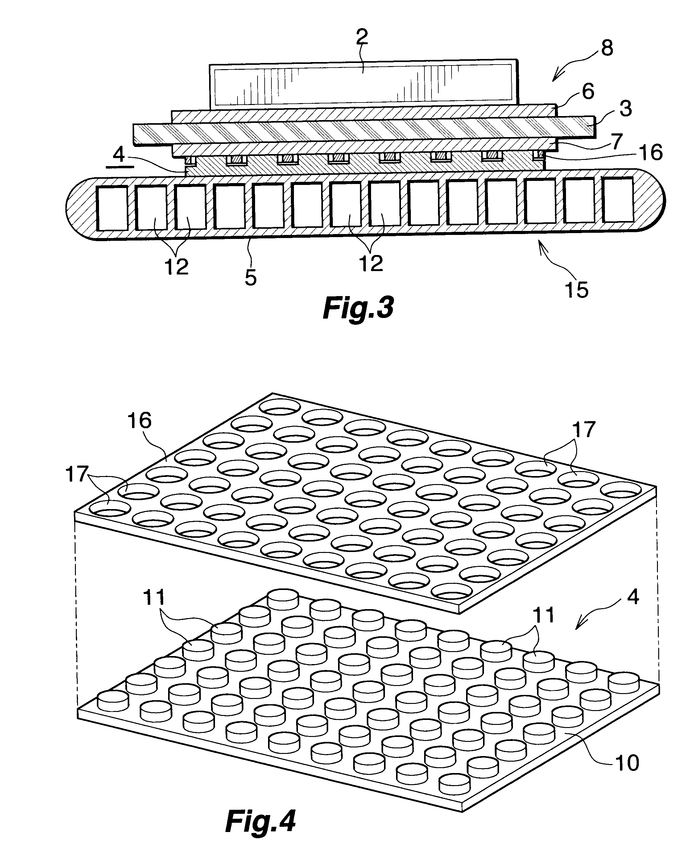
[0049]The present embodiment is shown in FIGS. 3 and 4.
[0050]FIG. 3 shows a portion of a power module which uses a heat radiator of Embodiment 2. FIG. 4 shows a stress relaxation member of the heat radiator of Embodiment 2.
[0051]In FIGS. 3 and 4, the stress relaxation member 4 similar in constitution to that of Embodiment 1, and a thermal-conduction plate 16 formed of a high-thermal-conduction material; herein, aluminum, and having a plurality of through-holes 17 allowing the respective projections 11 of the stress relaxation member 4 to extend therethrough are disposed between the power module substrate 8 and the heat sink 5 in a heat radiator 15. In Embodiment 2, the projections 11 of the stress relaxation member 4 are not formed in a staggered arrangement, but are formed in a grid arrangement. The thermal-conduction plate 16 is disposed above the plate-like body 10 of the stress relaxation member 4 in such a manner that the projections 11 extend through the respective through-hol...
embodiment 3
[0056]The present embodiment is shown in FIGS. 5 and 6.
[0057]FIG. 5 shows a portion of a power module which uses a heat radiator of Embodiment 3. FIG. 6 shows a stress relaxation member of the heat radiator of Embodiment 3.
[0058]In FIGS. 5 and 6, two stress relaxation members 4 similar in constitution to that of Embodiment 1 are disposed between the power module substrate 8 and the heat sink 5 in a heat radiator 20. The upper stress relaxation member 4 is disposed with the projections 11 facing downward, and the lower stress relaxation member 4 is disposed with the projections 11 facing upward. In Embodiment 3, the projections 11 of the two stress relaxation members 4 are not formed in a staggered arrangement, but are formed in a grid arrangement. The upper surface of the plate-like body 10 of the upper stress relaxation member 4 is brazed to the metal layer 7 of the power module substrate 8, and the lower surface of the plate-like body 10 of the lower stress relaxation member 4 is ...
PUM
 Abstract
Description
Claims
Application Information
 - R&D
- Intellectual Property
- Life Sciences
- Materials
- Tech Scout
- Unparalleled Data Quality
- Higher Quality Content
- 60% Fewer Hallucinations
Browse by: Latest US Patents, China's latest patents, Technical Efficacy Thesaurus, Application Domain, Technology Topic, Popular Technical Reports.
© 2025 PatSnap. All rights reserved.Legal|Privacy policy|Modern Slavery Act Transparency Statement|Sitemap|About US| Contact US: help@patsnap.com


