Portable coordinate measurement machine

Inactive Publication Date: 2006-01-26
FARO TECH INC
View PDF99 Cites 49 Cited by
  • Summary
  • Abstract
  • Description
  • Claims
  • Application Information

AI Technical Summary

Benefits of technology

[0011] In accordance with the present invention, a portable CMM comprises an articulated arm having jointed arm segments. In one embodiment, the arm segments include bearing/encoder cartridges which are attached to each other at predetermined angles using a dual socket joint. Each cartridge contains at least one, and preferably two, preloaded bearing assembl

Problems solved by technology

The controller mounted to the arm is used to run the executable program but

Method used


Image

  • Portable coordinate measurement machine
  • Portable coordinate measurement machine
  • Portable coordinate measurement machine

Examples


Embodiment Construction

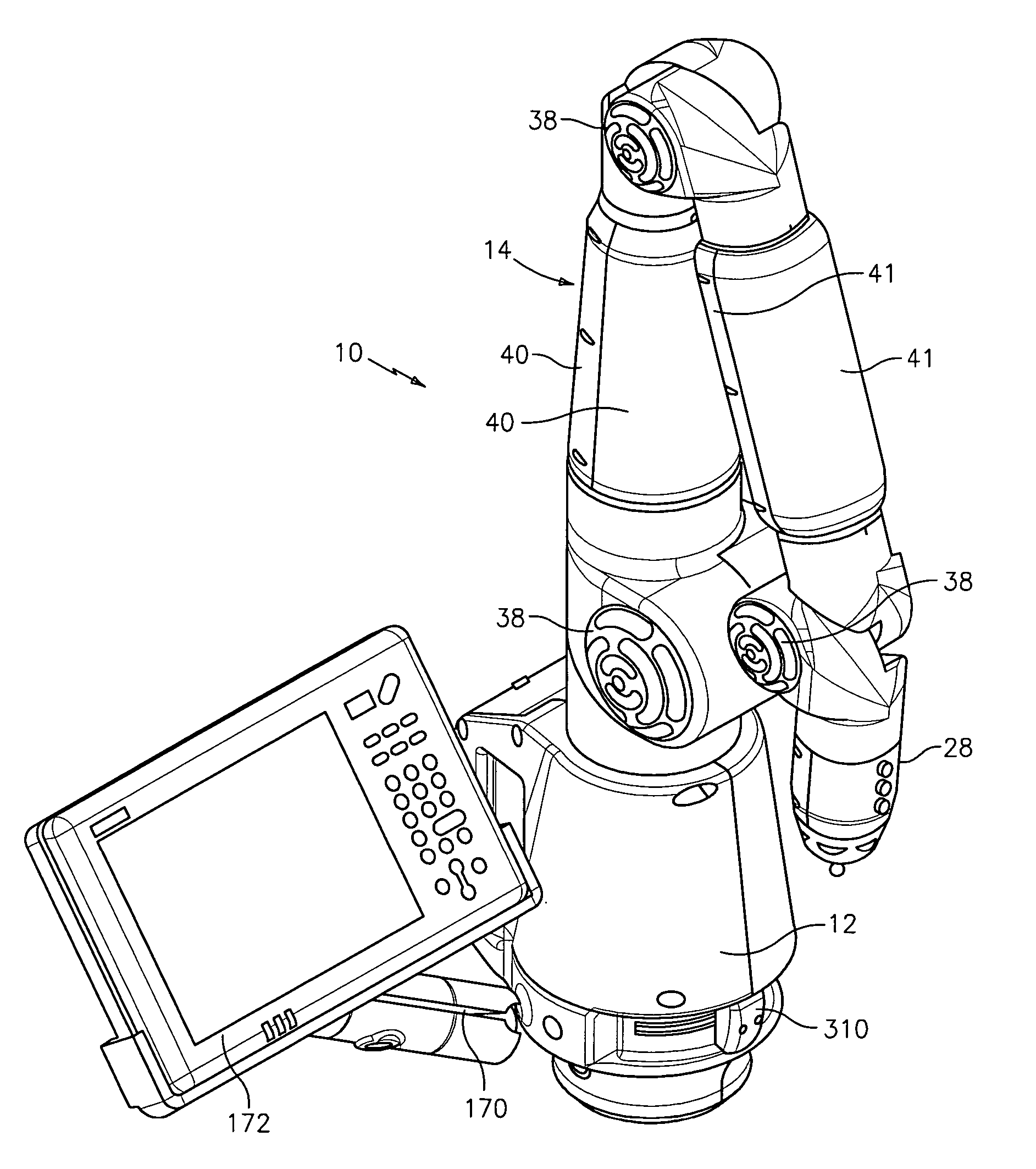
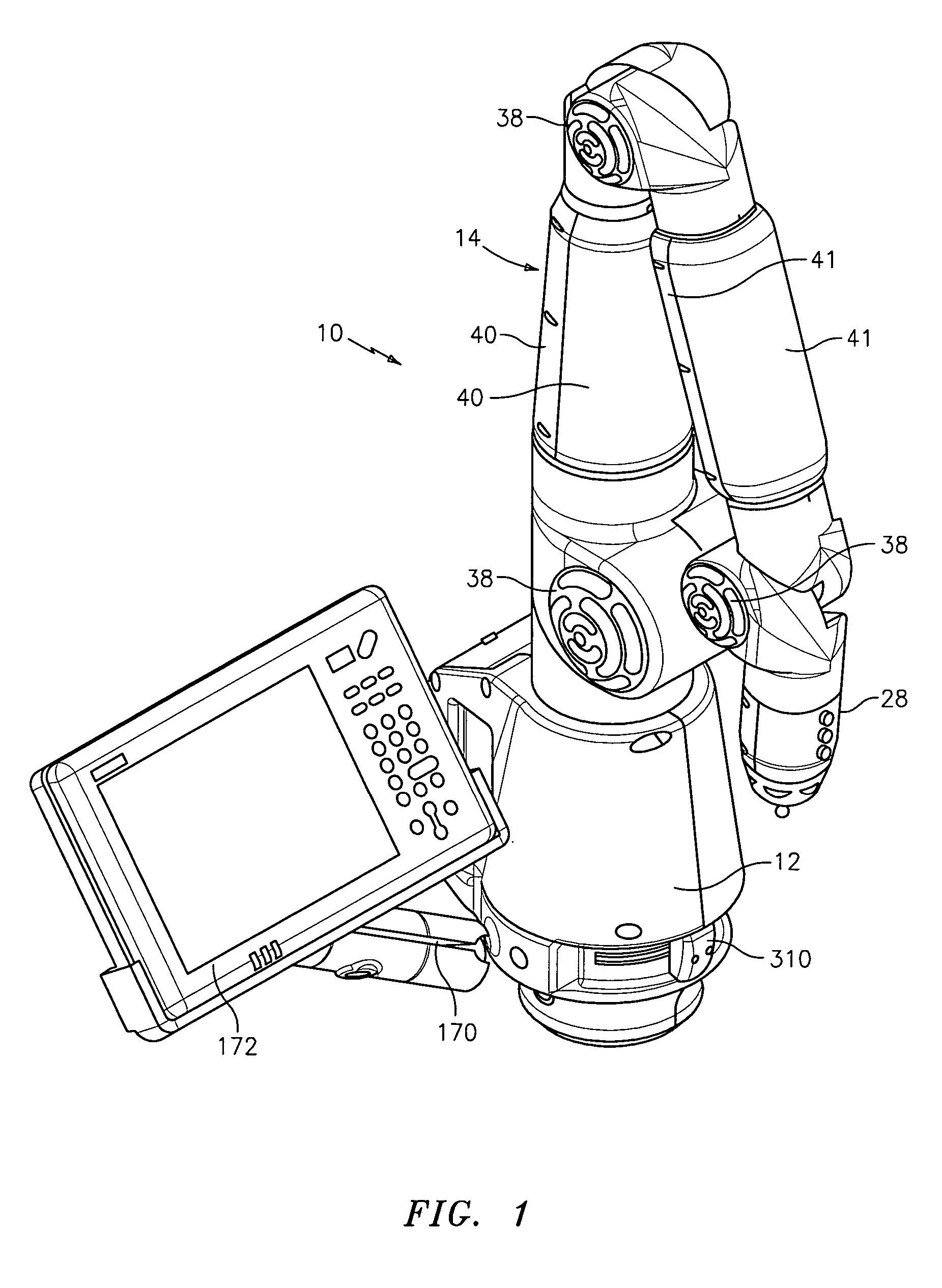
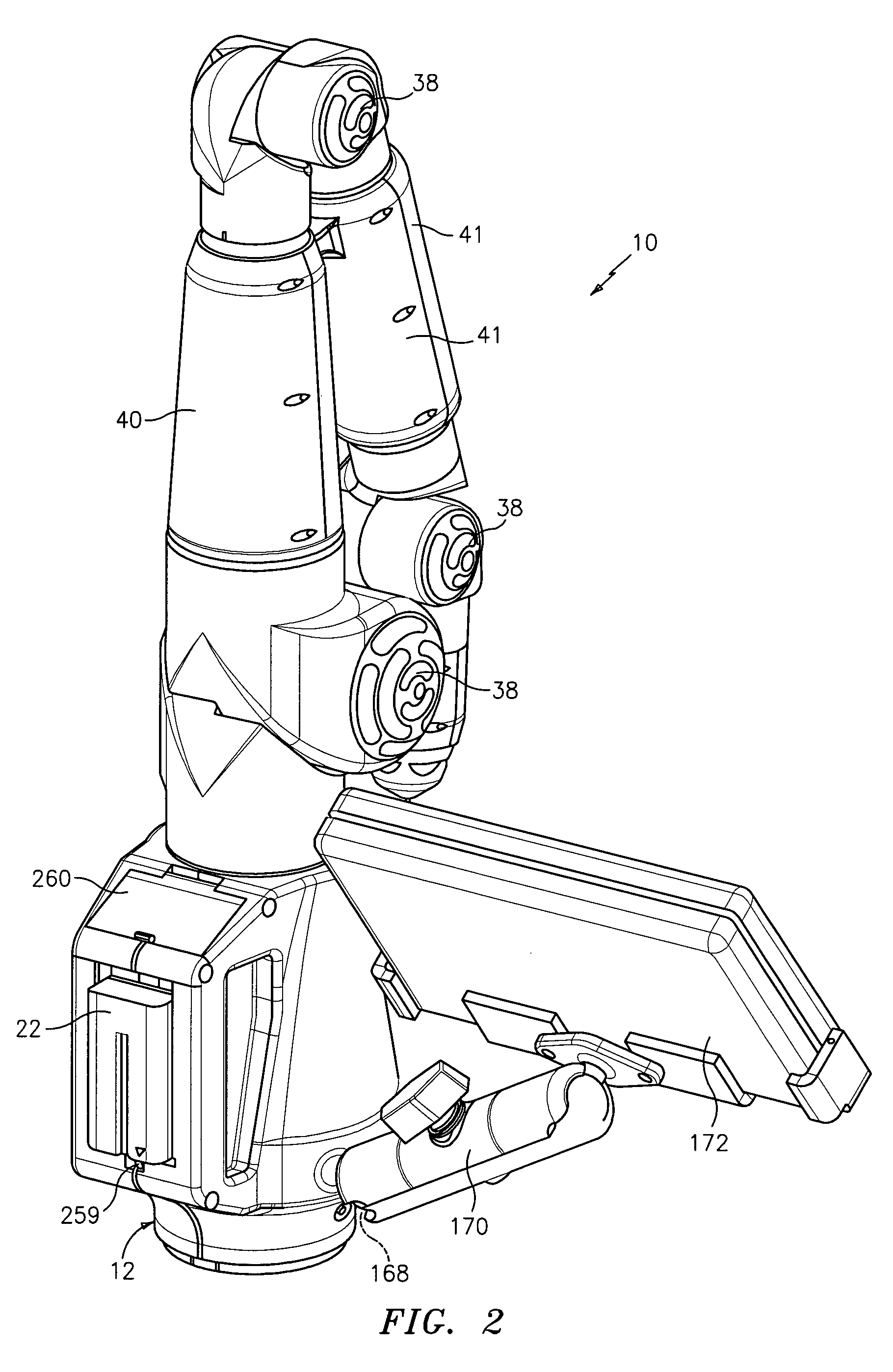
[0080] Referring first to FIGS. 1-3, the CMM of the present invention is shown generally at 10. CMM 10 comprises a multijointed, manually operated, articulated arm 14 attached at one end to a base section 12 and attached at the other end to a measurement probe 28. Arm 14 is constructed of basically two types of joints, namely a long joint (for swivel motion) and a short joint (for hinge motion). The long joints are positioned substantially axially or longitudinally along the arm while the short joints are preferably positioned at 90° to the longitudinal axis of the arm. The long and short joints are paired up in what is commonly known as a 2-2-2 configuration (although other joint configurations such as 2-1-2, 2-1-3, 2-2-3, etc. may be employed) Each of these joint pairs are shown in FIGS. 4-6.

[0081]FIG. 4 depicts an exploded view of the first joint pair, namely long joint 16 and short joint 18. FIG. 4 also depicts an exploded view of the base 12 including a portable power supply e...


PUM


Abstract

A portable coordinate measurement machine comprises an articulated arm having jointed arm segments. The jointed arm segments include a rotatable shaft, at least two spaced bearings and a housing surrounding the bearings and shaft wherein races for the bearings are formed by at least one of the following: (1) the shaft constitutes the inner race of at least one of the two bearings and (2) the housing constitutes the outer race of at least one of the two bearings.

Description

CROSS-REFERENCE TO RELATED APPLICATION [0001] This application is a continuation-in-part of application Ser. No. 11 / 028,844 filed Jan. 4, 2005, which is a continuation of application Ser. No. 10 / 366,680 filed Feb. 13, 2003 and claims the benefit of provisional application Nos. 60 / 357,599 filed Feb. 14, 2002 and 60 / 394,908 filed Jul. 10, 2002, all of the contents of both provisional applications being incorporated herein by reference.BACKGROUND OF THE INVENTION [0002] 1. Field of the Invention [0003] The invention relates in general to coordinate measurement machines (CMMs) and in particular to portable CMM's having an articulated arm. [0004] 2. Prior Art [0005] Currently, portable articulated arms are provided as a measurement system with a host computer and applications software. The articulated arm is commonly used to measure points on an object and these measured points are compared to computer-aided design (CAD) data stored on the host computer to determine if the object is with...

Claims


Application Information

Patent Timeline
IPC IPC(8): G01B5/004
CPCG01B5/008
Inventor RAAB, SIMONSAJEDI, SEYED ALIBARBER, MARC
Owner FARO TECH INC
Why Eureka
Try Eureka