

Simplified method for making rolled al-zn-mg alloy products, and resulting products
a technology of rolled al-zn-mg alloy and rolled alloy, which is applied in the field of alloys of the al-zn-mg type, can solve the problems of stress corrosion and layer corrosion of alloys, and achieve the effect of improving the quality of the produ
- Summary
- Abstract
- Description
- Claims
- Application Information
AI Technical Summary
Benefits of technology
Problems solved by technology
Method used
Image

Examples
example 1
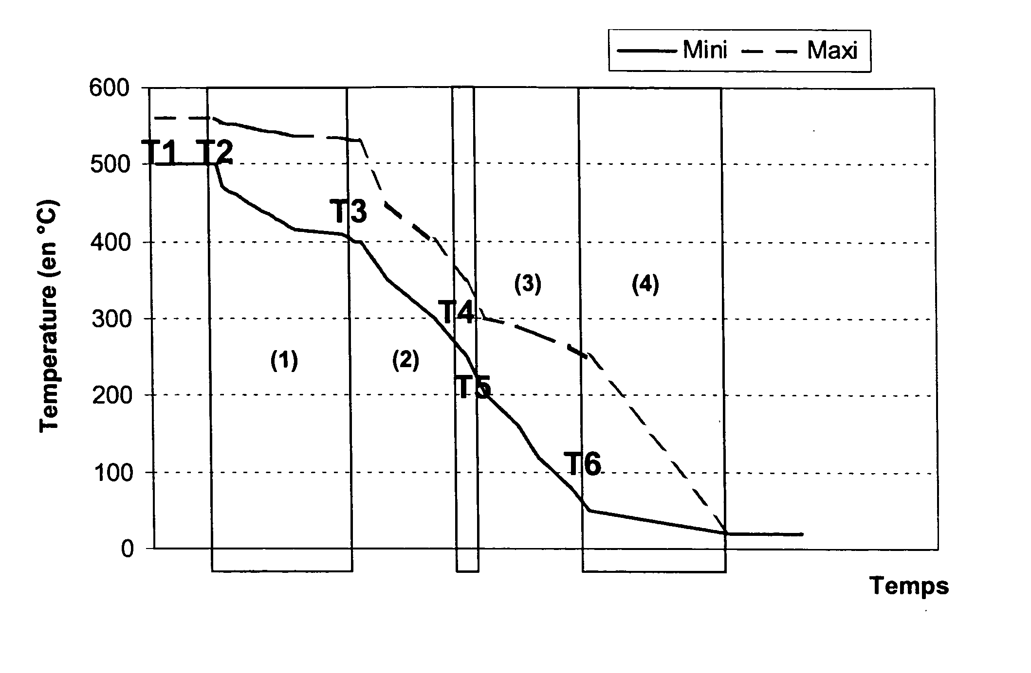
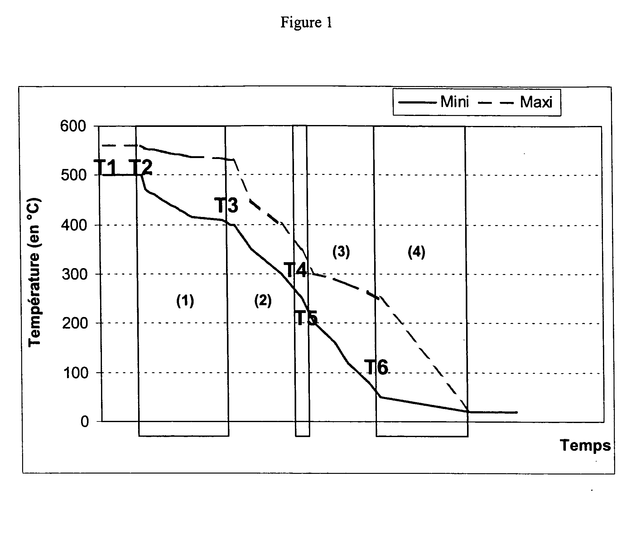
[0103] This example corresponds to a transformation range as in the prior art. It was generated by the semi-continuous casting of two plates A and B. Their composition is given in Table 2. Chemical analysis of the elements was carried out by X-ray fluorescence (for elements Zn and Mg) and spark spectroscopy (other elements) on a slug obtained from liquid metal taken from the main runner.
[0104] The rolling plates were reheated for 22 hours at 530° C. and hot-rolled as soon as they had reached, when leaving the kiln, a temperature of 515° C. The hot-rolled strips were coiled at 6 mm thickness, the process being conducted in such a way that the temperature, measured on the lips of the coil after being fully wound (at half-thickness of winding) is between 265° C. and 275° C., this value being the average between two measurements made at the two edges of the coil. After hot-rolling, the coils were split into sheets and part of the sheets obtained was cold-rolled to a thickness of 4 mm. ...
example 2
[0109] The sheets emanating from example 1, rolled to 6 mm and solution treated at 560° C., denoted ACH and BCH, were welded in the T6 state. Welding was done in the Transverse-Long direction, with a double Vee groove, by a semi-automatic smooth current MIG process, with a 5183 alloy welding wire (Mg 4.81%, Mn 0.651%, Ti 0.120%, Si 0.035%, Fe 0.130%, Zn 0.001%, Cu 0.001%, Cr 0.075%) of 1.2 mm diameter, supplied by the company Soudure Autogène Franaise.
[0110] The tensile test pieces (width 25 mm, symmetrically shaved bead, effective length of test piece and length of extensometer equal to (W+2 e) where W denotes the width of the bead and e the thickness of the test piece) were taken in the long direction, perpendicularly to the weld, in such a way that the joint is located in the middle. Characterisation was carried out 19, 31 and 90 days after welding, since the man skilled in the art knows that for this type of alloy, the mechanical properties after welding increase strongly durin...
example 3
[0113] This example corresponds to the present invention. By semi-continuous casting a plate C was generated. Its composition is identical to that of the plate B emanating from example 1. The plate was hot-rolled, after reheating for 13 hours at 550° C. (point duration) followed by a rolling point at 540° C. The first step, in the reversing mill, brought the plate to a thickness of 15.5 mm, the output temperature of the rolling mill being about 490° C. The rolled plate was then cooled by spraying and by natural convection to a temperature of about 260° C. At this temperature it was put into a tandem mill (3 cages), rolled to the final thickness of 6 mm, and coiled. The winding temperature of the coil, measured as in example 1, is about 150° C. Once naturally cooled, the coil was cut up into sheets. These were levelled and were subjected to no further operation of distortion.
[0114] As in examples 1 and 2, the sheets obtained (identified as “C”) were characterised in unwrought manufa...
PUM
| Property | Measurement | Unit |
|---|---|---|
| temperature T1 | aaaaa | aaaaa |
| temperature T6 | aaaaa | aaaaa |
| thickness | aaaaa | aaaaa |
Abstract
Description
Claims
Application Information