
Serial data gauge

a technology of serial data and gauges, applied in the field of gauges, can solve the problems of cumbersome and messy addition of additional gauges, increase the difficulty of installation, and reduce the accuracy of the measurement, and achieve the effect of greater detail and clarity

Inactive Publication Date: 2006-01-26
INNOVA ELECTRONICS
View PDF12 Cites 58 Cited by
  • Summary
  • Abstract
  • Description
  • Claims
  • Application Information

AI Technical Summary

Benefits of technology

[0013] The gauge which is a subject matter of the present invention based on its appearance may be characterized as a stylish yet simple design, as shown in the Figures. Yet, the gauge is a robust device which is easy to install, transferable, reconfigurable, intuitive, customizable, easy to navigate, helpful and ingenious.
[0016] The quick and easy installation of the gauge with the connector to the DLC in combination with the removeably attachable feature discussed above enables the gauge of the present invention to be transported from automobile to automobile. This transportability or transferability of the gauge between automobiles may be particularly useful in a rental car situation or single driver who owns two different types of vehicle situation. Moreover, the ease by which the gauge may be mounted and placed in communication with the OBD broadens the market for this gauge. In particular, if the gauge requires expert installation, then the gauge as a total package (including installation) becomes more expensive. As such, since the gauge of the present invention may conceivably be installed by a do it yourselfer, the market for the gauge is limited by the number of automobiles on the road. Moreover, the single wire which may connect the gauge to the OBD is not noticeable to detract from the interior's attractiveness. Even this single wire may be eliminated by the use of wireless communication technology between the gauge and the gauge's connector.
[0020] A second format comprises a series of layered screens. The top most layer may comprise a set of icons that identify the five different modes identified above. The second layer may display a single operating condition / parameter within each of the five different modes. Upon depressing the operating condition / parameter, a detail screen of the mode may be displayed or a component screen may be displayed. In this regard, the layered screens provide a greater amount of detail and clarity to the user as the user navigates through the layered screens. In this second format, the user may customize the second layer (i.e., the home screen) in that a selected operating condition / parameter within each of the five modes may be displayed on the monitor simultaneously.
[0026] The method by which the gauge efficiently communicates with the OBD will now be discussed. In particular, the gauge queries the OBD in batch requests. In other words, the gauge sends a request to the OBD requesting the OBD to provide data at particular PIDs (i.e., parameter identification). The data at the PIDs relate to the operating conditions / parameters of the automobile. However, as stated above, the OBD is a diagnostic tool and is designed for the purpose of helping the automobile produce lower emissions. In this regard, the batch request sent by the gauge may be ignored when received by the OBD if the OBD is processing emissions related issues internally. As such, the data sent to the gauge may be late or untimely or unusable by the gauge. The gauge of the present invention divides the batch into smaller batches. These smaller batches are sent at different time intervals and at different frequencies in order to reduce the possibility that the OBD processor cannot process both its internal emissions related issues as well as the batch request. Hence, the gauge transforms the OBD which is diagnostic tool for lowering automobile emissions to robust multi functional gauge that may be transferred from auto to auto with an easy to navigate format. Simply put, the gauge of the present invention is a robust state of the art gauge.

Problems solved by technology

Accordingly, these additional gauges must be hard wired to the respective automobile component which may be difficult even for an expert and unattractive.
Moreover, as the numbers of additional gauges are installed, the difficulty of the installation increases as well as its unattractiveness because of the need for additional wires and modifications to the vehicle.
Simply put, frequently, adding additional gauges above the standard gauges that are installed by the manufacturer is cumbersome and messy, and drivers are hesitant to add additional gauges to the automobile even though it may be safer to do so such as in the towing situation above.
Furthermore, the standard gauges are geared to general use of the automobile, and these gauges are not function specific or suited to a particular taste of a driver.
For example, as stated above, the automobile may primarily be used for towing (i.e., function of the automobile) but gauges useful to make the towing automobile safer are not installed by the manufacturer.
This may create a difficult installation and an unattractive interior.
Simply put, gauges on the market today are not geared toward the function of the automobile or the taste of the driver.
Moreover, the gauges that are typically being sold are fixed and are not customizable per the individual taste of the driver or function of the automobile.
In this regard, the gauges sold today are not customizable such that only operating conditions of the vehicle useful for towing are displayed on a single gauge when the automobile is being used for towing and operating conditions related to the performance of the automobile are displayed on the gauge when the driver desires to display such operating conditions.
Simply put, these gauges are not customizable to a particular taste of a driver or function of the automobile.
In sum, first, the gauges in the market are difficult to install, and as the number of gauges installed on the automobile increases, the difficulty of installing the gauges increases as well as the unattractiveness of the installed gauges.
Moreover, if the gauge is easy to install such that anyone could install it, then drivers who use their automobiles for towing would be more apt to install the gauge, instead of being hesitant to install the gauge because of the difficulty of installing the gauge.
Second, the gauges in the market today are not geared to a particular function of the automobile or taste of the driver.
Third, gauges sold in the market today are not customizable per the function of the automobile nor the taste of the driver.

Method used


Image

  • Serial data gauge
  • Serial data gauge
  • Serial data gauge

Examples


Embodiment Construction

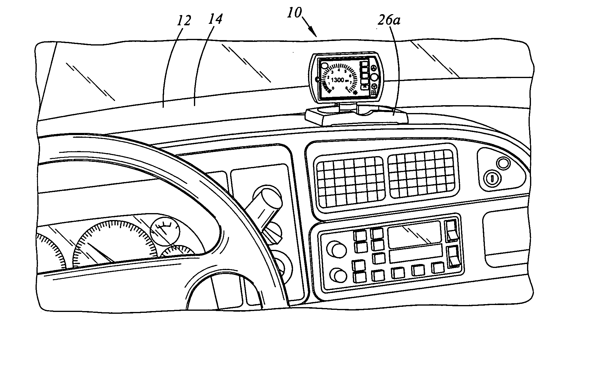
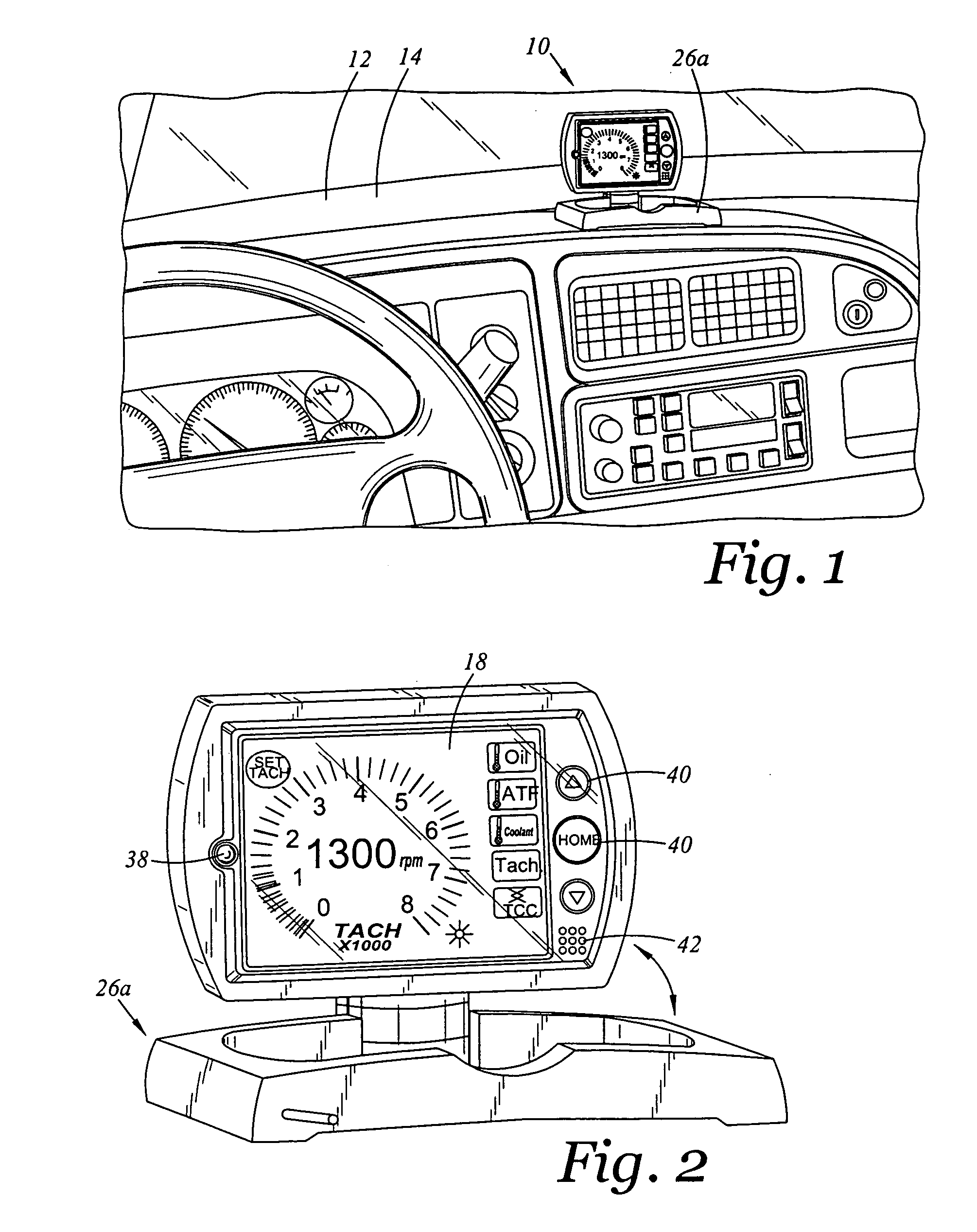
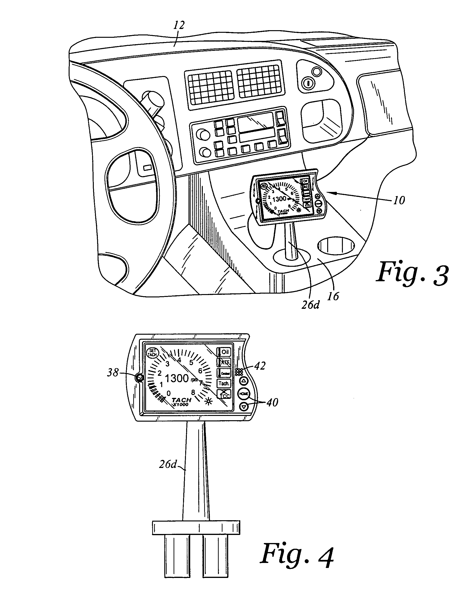
[0053] The drawings shown herein are for the purposes of illustrating the preferred embodiments of the present invention and are not meant to limit in any respect the various aspects of the present invention described in this specification. For example, FIGS. 1-4 illustrate two different methods of mounting a gauge 10 in an automobile 12 such that the gauge 10 is viewable by a driver. In particular, FIG. 1 illustrates the gauge 10 being fixedly attached to a dashboard 14 of the vehicle 12, and in contrast, FIG. 3 illustrates the gauge 10 being removably insertable into a cupholder 16 of the automobile 12. In this regard, the methods of mounting the gauge 10 to the automobile 12 are not limited to the methods disclosed in this specification (i.e., dash mounted or cup holder mounted); rather the methods disclosed to mount the gauge 10 to the automobile 12 are illustrative and not exclusive to the methods by which the gauge 10 may be mounted to the automobile 12. Similarly, FIGS. 5-17 ...


PUM


Abstract

An instrument is provided which is in electronic communication with an on board diagnostic system (OBD) of an automobile. The instrument selectively queries the OBD with batch requests for the purpose of reducing a processing load placed on the OBD PCM. The instrument obtains numerous operating conditions through the OBD, and displays the operating conditions in an intuitive format. The operating conditions may be grouped into five different modes, and the five most relevant operating conditions within each mode may be displayed on the monitor either by default or through customization by the user.

Description

CROSS-REFERENCE TO RELATED APPLICATIONS [0001] Not Applicable STATEMENT RE: FEDERALLY SPONSORED RESEARCH / DEVELOPMENT [0002] Not Applicable BACKGROUND OF THE INVENTION [0003] The present invention relates to a gauge, and more particularly, to a gauge that is easily installable to an automobile through its on board diagnostic system, has a monitor that is removeably attachable to the automobile, and may display numerous operating conditions formatted in an intuitive format which is customizable. [0004] A gauge is standard component on every vehicle sold in the United States. For example, a gauge that is standard on every automobile is a speedometer and an odometer. These gauges are installed by the manufacturer of the automobile at the time of manufacture. Another standard gauge of every automobile is a Fuel level indicator. This gauge also is installed by the manufacturer at the time of manufacture. In other cases, the manufacturer may place temperature or pressure sensor in the engi...

Claims


Application Information

Patent Timeline
Patent Type & Authority Applications(United States)
IPC IPC(8): B60Q1/00
CPCB60K35/00G01D7/02G01P1/08G07C5/0825B60K35/60B60K35/213B60K35/22B60K35/53B60K35/654
Inventor ANDREASEN, KEITHRICH, DAVID
Owner INNOVA ELECTRONICS
Learn More