
Panoramic vision system and method

Active Publication Date: 2006-01-26
GEO SEMICONDUCTOR INC
View PDF15 Cites 296 Cited by
  • Summary
  • Abstract
  • Description
  • Claims
  • Application Information

AI Technical Summary

Benefits of technology

[0031] The present invention in its first embodiment provides a vehicle vision system covering up to 360° horizontal field of view, and up to 180° vertical field of view coverage, with emphasis on the rear, side, and corner views. The situational display image can be integrated with other vehicle information data such as vehicle status or navigation data. The image is preferably displayed on the front panel, contiguous with the driver's field of view. Additional views can be displayed to improve coverage and flexibility such as interior dashboard corner displays that substitute mirrors, eliminating exposure to the external elements and wind drag. The system is adapted to reconfigure the display and toggle between views based on control inputs, when one view becomes more critical than others.
[0034] In yet another embodiment, the invention provides a videoconference vision system producing a wide view of up to 180° or a circular view of up to 360°. In this embodiment, the invention facilitates viewing the participants of a conference or a gathering and provides ability to zoom in on speakers with a single camera.

Problems solved by technology

To minimize the number of cameras and cost, cameras with panoramic lens enable a wide field of view but will have distortions due to inherent geometric shape and optical non-linearity.
They tend, however, to distort images, especially the edges.
In any type of lens, there are also optical distortions caused by tangential and radial lens imperfections, lens offset, focal length of the lens, and light falloff near the outer portions of the lens.
In a vision system, there are yet other types of image distortions caused by luminance variations and color aberrations.
These distortions affect the quality and sharpness of the image.
Prior art panoramic vision systems do not remove image distortions while accurately blending multiple images.
Distorted images and discontinuity between multiple images slow down the operator's visual cognizance, and as such, her / his situational awareness, resulting in potential errors.

Method used


Image

  • Panoramic vision system and method
  • Panoramic vision system and method
  • Panoramic vision system and method

Examples


Embodiment Construction

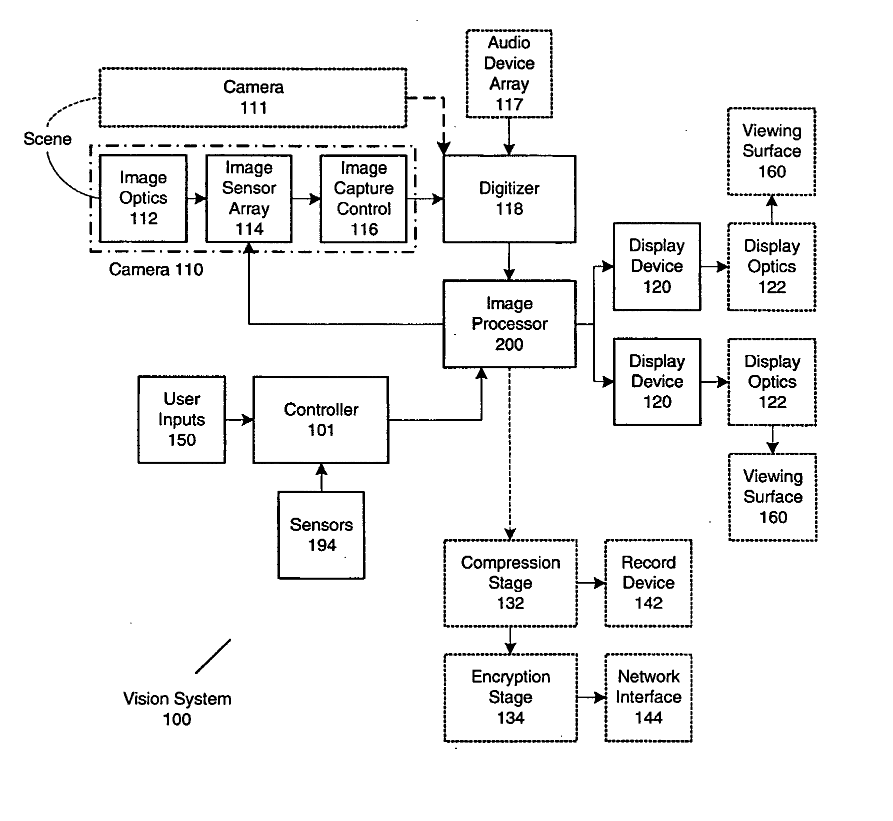
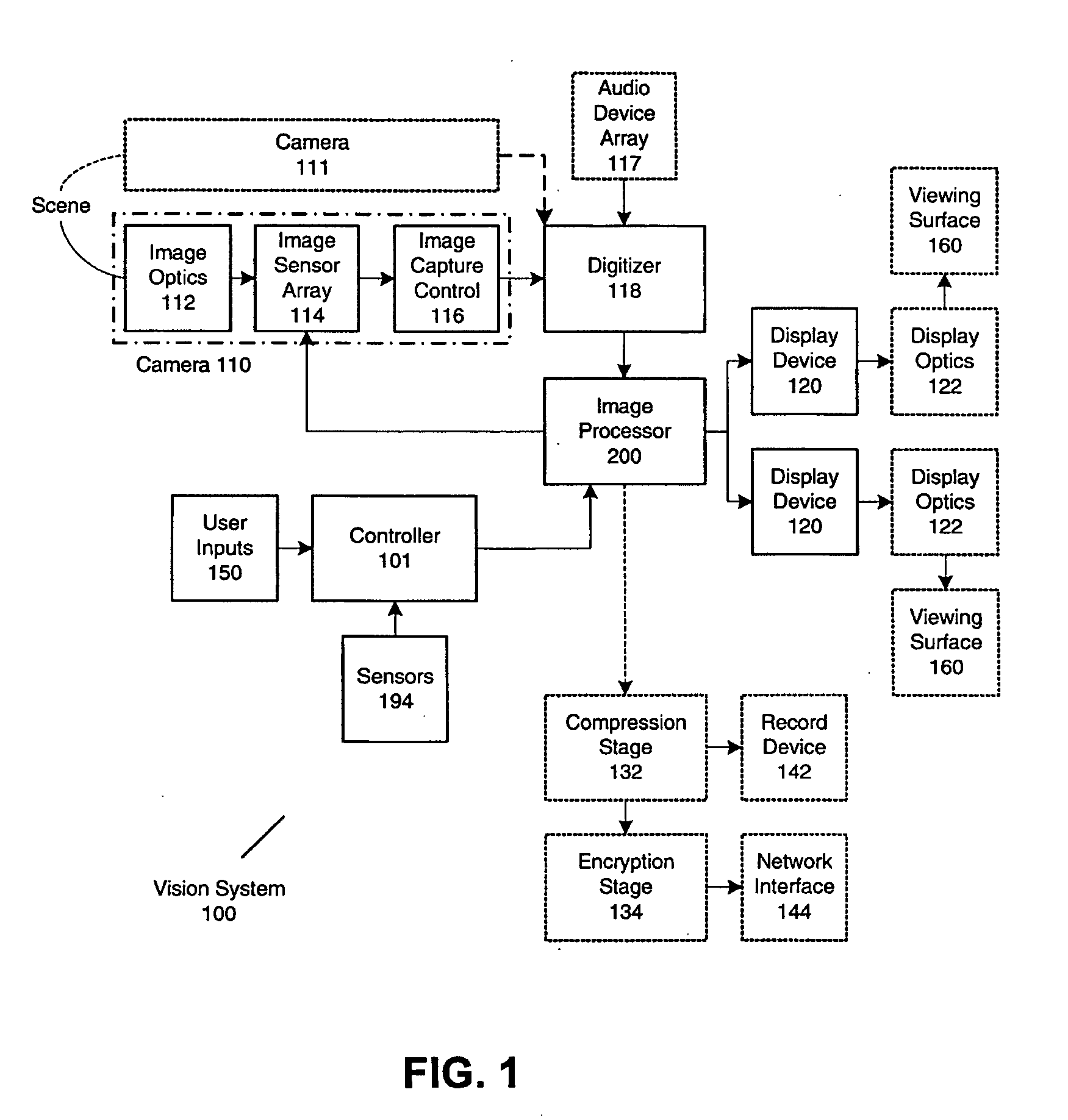
[0056] Built in accordance with the present invention, FIG. 1 shows the overall structure of vision system 100. It comprises a plurality of image acquisition devices like camera 110 to capture image frames, digitizer 118 to convert image frame data to digital image data, image processor 200 to adjust luminance and correct image distortions and form a composite image from digital image data and control parameters, controller 101 to relay user and sensor parameters to image processor 200, and display device 120 to display the composed image for viewing on the viewing surface 160. The final composed image in the present invention covers up to 360° including several specific regions of interest and is significantly distortion free. It greatly enhances situational awareness.

[0057] Camera 110 in FIG. 1 comprises image optics 112, sensor array 114 and image capture control 116. For applications requiring wide area coverage, image optics 112 may use a wide angle lens to minimize the number...


PUM


Abstract

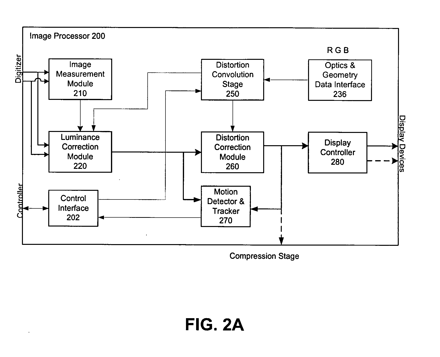
A distortion corrected panoramic vision system and method provides a visually correct composite image acquired through wide angle optics and projected onto a viewing surface. The system uses image acquisition devices to capture a scene up to 360° or 4π steradians broad. An image processor corrects for luminance or chrominance non-uniformity and applies a spatial transform to each image frame. The spatial transform is convolved by concatenating the viewing transform, acquisition geometry and optical distortion transform, and display geometry and optical transform. The distortion corrections are applied separately for red, green, and blue components to eliminate lateral color aberrations of the optics. A display system is then used to display the resulting composite image on a display device which is then projected through the projection optics and onto a viewing surface. The resulting image is visibly distortion free and matches the characteristics of the viewing surface.

Description

FIELD OF THE INVENTION [0001] This invention relates to vision systems, particularly to panoramic vision systems with image distortion correction. BACKGROUND OF THE INVENTION [0002] Improved situational awareness is increasingly required for many applications including surveillance systems, videoconference vision systems, and vehicle vision systems. Essential to such applications is the need to monitor a wide operating area and to form a composite image for easy comprehension in different user modes. To minimize the number of cameras and cost, cameras with panoramic lens enable a wide field of view but will have distortions due to inherent geometric shape and optical non-linearity. In a surveillance application, multiple panoramic cameras may cover the entire exterior and interior area of a building, and the system can provide continuous view of the area and, manually or automatically, track objects through the area. [0003] In a vehicle vision system, multiple panoramic cameras can ...

Claims


Application Information

Patent Timeline
IPC IPC(8): H04N7/14H04N7/00H04N7/18H04N9/47H04N5/217
CPCB60R1/00B60R2300/105B60R2300/302B60R2300/303B60R2300/8026H04N7/181H04N5/232H04N5/23238H04N7/147H04N7/15H04N5/217H04N23/81H04N23/698H04N23/635B60R1/27
Inventor LEE, LOUIEVAKILI, MASOUD
Owner GEO SEMICONDUCTOR INC
Learn More