Laser-scanning examination apparatus

a laser scanning and examination apparatus technology, applied in the direction of optical radiation measurement, fluorescence/phosphorescence, instruments, etc., can solve the problems of single-mode fiber, inability to efficiently carry out measurement, and the measurement head itself, so as to reduce the loss of fluorescence intensity and compact the configuration of the measurement head

Inactive Publication Date: 2006-01-26
OLYMPUS CORP
View PDF3 Cites 47 Cited by
  • Summary
  • Abstract
  • Description
  • Claims
  • Application Information

AI Technical Summary

Benefits of technology

[0009] The present invention has been conceived in light of the situation described above, and an object thereof is to provide laser-scanning examination apparatus that can reduce the loss of fluorescence intensity obtained from a specimen, while irradiating the specimen with ultrashort-pulse laser light produced by a laser light source, thus enabling the acquisition of bright fluorescence images and that can make the configuration of the measurement head more compact.

Problems solved by technology

However, the single-mode fiber suffers from the drawback that it is not possible to carry out measurement efficiently because the core diameter is narrow and thus fluorescence returning from the specimen is spatially confined.
In order to more efficiently measure the fluorescence, it is preferable to dispose the photomultiplier tube directly after the objective lens in the measurement head; in such a case, however, since the photomultiplier tube is comparatively large, the measurement head itself becomes larger and therefore is not suitable for use in applications where it needs to be disposed at various orientations and positions according to the examination site in the specimen, for example, when carrying out in-vivo examination of small laboratory animals.
Such light has a drawback in that it is not possible to efficiently generate the multiphoton-excitation effect.

Method used


Image

  • Laser-scanning examination apparatus
  • Laser-scanning examination apparatus
  • Laser-scanning examination apparatus

Examples


second embodiment

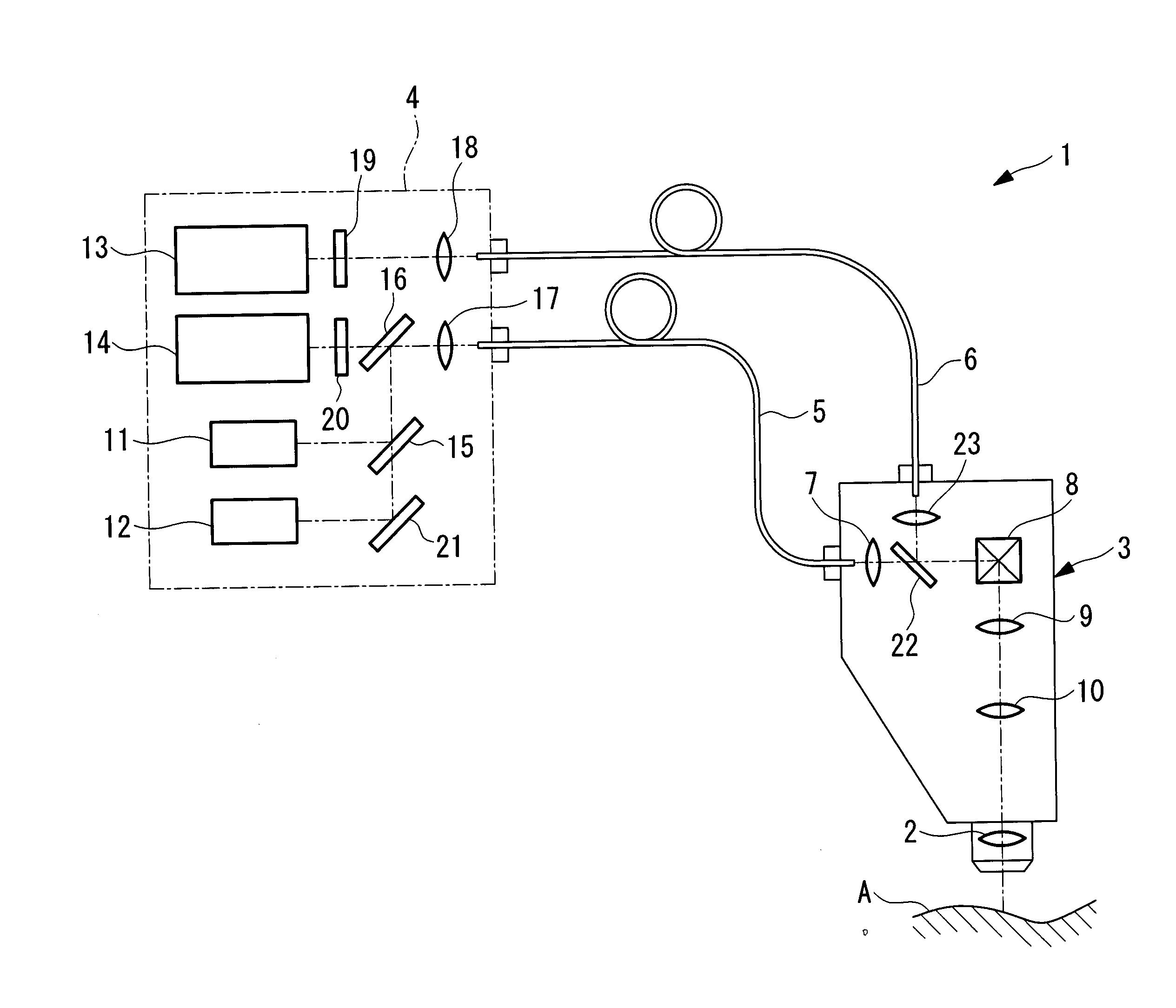
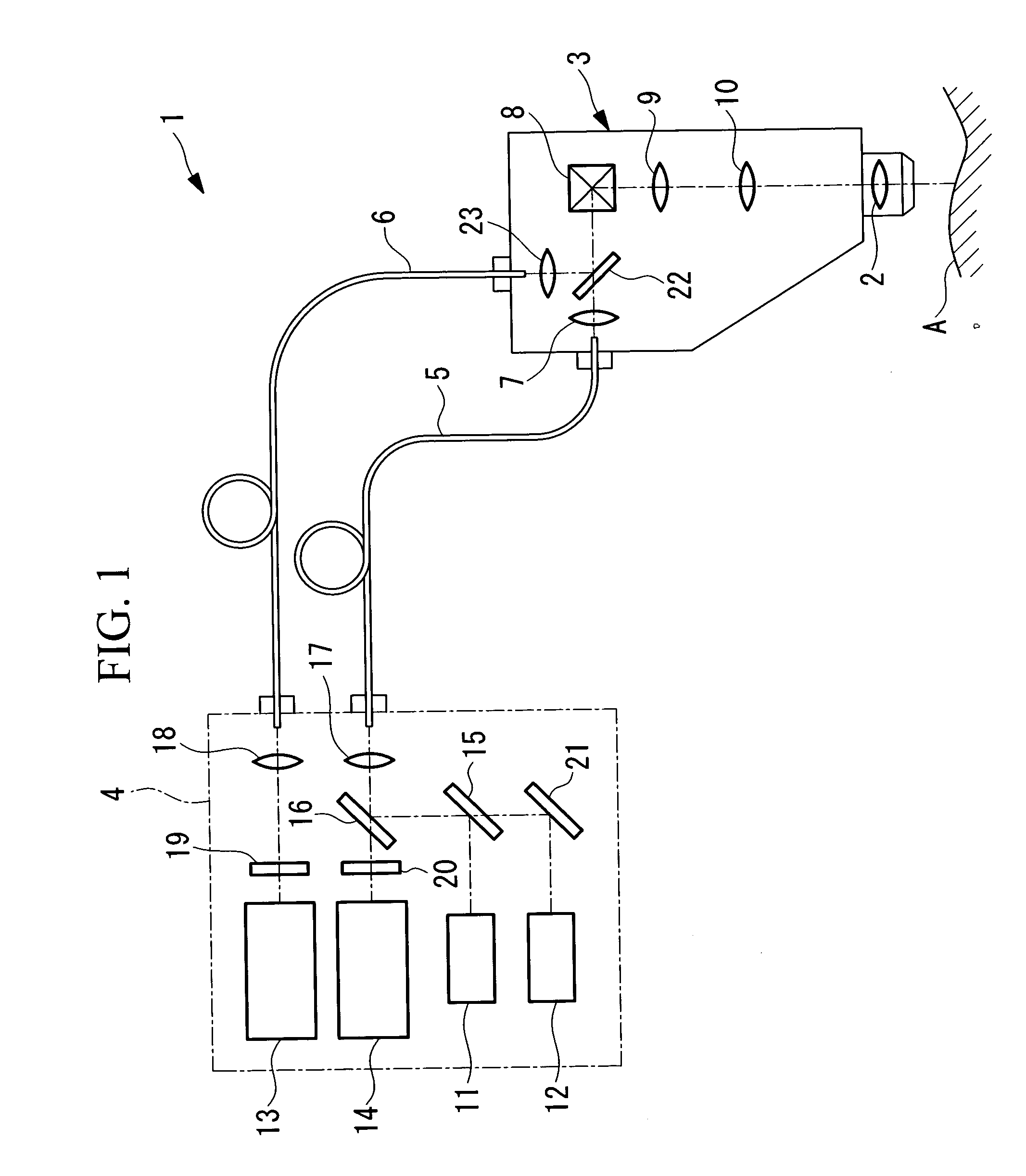
[0068] Next, a laser-scanning examination apparatus 30 according to the present invention will be described below with reference to FIG. 4.

first embodiment

[0069] In the description of this embodiment, parts having the same configuration as those in the laser scanning examination apparatus 1 shown in FIG. 1 are assigned the same reference numerals and a description thereof shall be omitted.

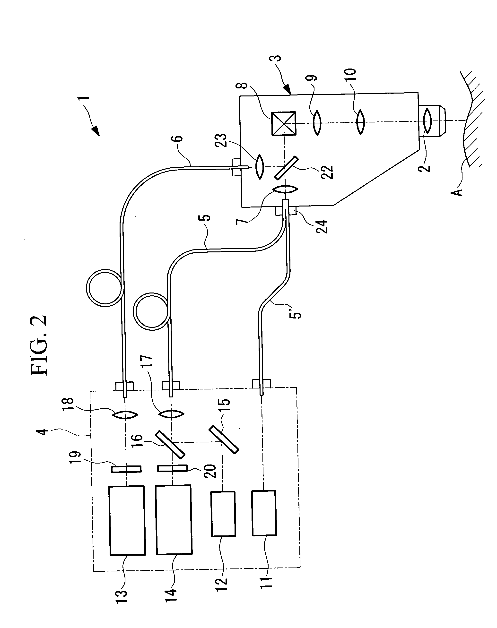
[0070] Whereas the laser-scanning examination apparatus 1 according to the first embodiment uses a single-mode fiber or a photonic crystal fiber as a first optical fiber 5, the laser-scanning examination apparatus 30 according to this embodiment differs in that it uses a first optical fiber 31 formed of a multi-mode fiber. Another difference is that, in the measurement head 3, a focusing lens 32 and a pinhole member 33 are disposed in front of a collimator lens 7 so as to oppose the light-emitting end of the first optical fiber 31.

[0071] The pinhole member 33 is disposed in the vicinity of the image formed by the focusing lens 32, and the diameter of the opening thereof is of a size that admits passage of only the central part of an image of the li...

third embodiment

[0086] Next, a laser-scanning examination apparatus 40 according to the present invention will be described with reference to FIGS. 6 and 7.

[0087] In the description of this embodiment, parts having the same configuration as those in the laser-scanning examination apparatus according to the first embodiment shown in FIG. 1 are assigned the same reference numerals, and a description thereof shall thus be omitted.

[0088] As shown in FIG. 6, in the laser-scanning examination apparatus 40 according to this embodiment, a second light source 12 that produces continuous-wave laser light includes two laser light sources 12a and 12b, whose optical axes are combined by a dichroic mirror 41. These laser light sources 12a and 12b have different wavelengths and they are alternately switched or used simultaneously when examining the specimen A, which is stained with two different dyes. Also, removable dichroic mirrors 42 and 42′ are disposed between a first optical detector 13 and a collimator le...


PUM


Abstract

The invention reduces the loss of fluorescence intensity obtained from a specimen to acquire clear fluorescence images when irradiating the specimen with ultrashort-pulse laser light produced by a laser light source. The invention provides a laser-scanning examination apparatus including a laser light source for producing ultrashort-pulse laser light; a laser light source for producing continuous-wave laser light; a measurement head including an optical scanning unit for scanning the laser light on a specimen and an objective optical system; an imaging unit for detecting return light from the specimen in response to the ultrashort-pulse laser light; and an imaging unit for detecting return light from the specimen in response to the continuous-wave laser light. The laser light sources and one imaging unit are connected to the measurement head by an optical fiber, and the other imaging unit is connected to the measurement head by another optical fiber with a larger core diameter.

Description

BACKGROUND OF THE INVENTION [0001] 1. Field of the Invention [0002] The present invention relates to a laser-scanning examination apparatus. [0003] This application is based on Japanese Patent Application No. 2004-217605, the content of which is incorporated herein by reference. [0004] 2. Description of Related Art [0005] Known apparatuses in the related art for observing cellular function and the like by irradiating a specimen, such as a living organism, from the surface thereof with excitation light and detecting fluorescence generated at a comparatively deep position below the surface of the specimen include multiphoton-excitation-type examination apparatuses (see, for example, Japanese Unexamined Patent Application Publication No. 2002-243641, page 3, etc.). [0006] This multiphoton-excitation-type examination apparatus has a configuration in which fluorescence emitted from the specimen is detected by an external photomultiplier tube that is connected via a single-mode fiber. [00...

Claims


Application Information

Patent Timeline
Patent Type & Authority Applications(United States)
IPC IPC(8): G01J3/30
CPCG01N21/6458G02B21/002G02B21/16G02B21/0076G02B21/0084G02B21/0064
Inventor TSUCHIYA, ATSUHIROKAWANO, YOSHIHIROTANIKAWA, YOSHIHISAHIRATA, TADASHI
Owner OLYMPUS CORP
Why Eureka
Try Eureka