Cerebral spinal fluid flow sensing device

Inactive Publication Date: 2006-01-26
MEDTRONIC INC
View PDF18 Cites 171 Cited by
  • Summary
  • Abstract
  • Description
  • Claims
  • Application Information

AI Technical Summary

Benefits of technology

[0011] In comparison to known techniques for monitoring and controlling CSF flow in an implanted shunt, various embodiments of the invention may provide one or more advantages. For example, the invention enables a care-giver to better evaluate the performance of the ventricular shunt, and take remedial action if necessary. For example, if the sensed CSF flow rate is too low, too high, or indicates a blockage, the care-giver may adjust a flow control valve or take other action to address the situation. In either case, the inven

Problems solved by technology

These problems include the insufficiency of ventricular size and ICP level, in some forms of hydrocephalus, as indicators of shunt performance.
In particular, ventricular size or ICP level may not be a reliable indicator of the actual CSF flow rate through the shunt.

Method used


Image

  • Cerebral spinal fluid flow sensing device
  • Cerebral spinal fluid flow sensing device
  • Cerebral spinal fluid flow sensing device

Examples


Embodiment Construction

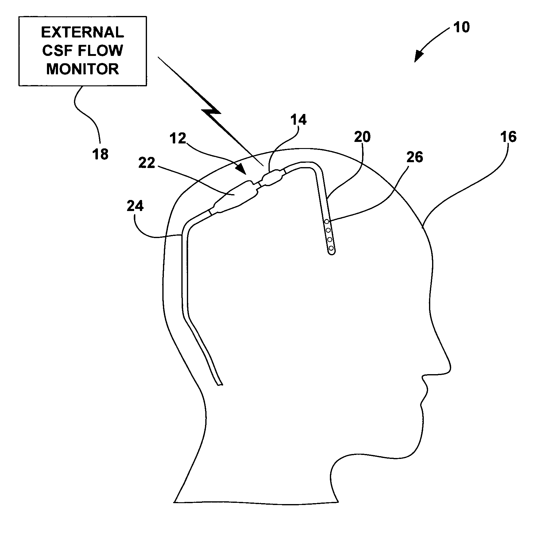
[0022]FIG. 1 is a schematic diagram illustrating a CSF flow monitoring system 10 having an implantable ventricular shunt 12 and a CSF flow sensor 14 in conjunction with a patient 16. CSF flow sensor 14 transmits CSF flow information to an external CSF flow monitor 18 via wireless telemetry. As shown in FIG. 1, shunt 12 is implanted within the cranium of patient 16, and includes a ventricular catheter 20, a CSF flow control valve 22 and a drainage catheter 24. Ventricular catheter 20, flow control valve 22 and drainage catheter 24 define a CSF flow path within shunt 12.

[0023] Ventricular catheter 20 may be bent and angled downward to extend into a brain ventricle. Alternatively, ventricular catheter 20 may be substantially straight, but couple to an angled coupling joint extending from control valve 22. Ventricular catheter 20 may define a plurality of holes 26 to receive CSF from a brain ventricle. Shunt 12 may be, for example, a ventriculoperitoneal shunt, a ventriculoatrial shunt...


PUM


Abstract

The disclosure is directed to an implantable device for sensing CSF flow through an implantable ventricular shunt. The sensing device is implanted with the CSF shunt, and includes a flow sensor to sense flow rate or shunt blockage. The sensing device is either placed within or adjacent to the fluid path through the shunt. The sensing device transmits the sensed flow rate to an external monitoring device by wireless telemetry. The sensing device may be integrally formed as part of the shunt, or clamped onto a portion of the shunt, in which case the sensing device may be resusable. An external monitor receives the transmitted flow signal and presents information based on the flow signal. The sensing device may be inductively powered or include its own power supply.

Description

[0001] This application claims the benefit of U.S. provisional application No. 60 / 589,350, filed Jul. 20, 2004, the entire content of which is incorporated herein by reference.FIELD OF THE INVENTION [0002] The invention relates to medical devices and, more particularly, devices for draining cerebrospinal fluid (CSF). BACKGROUND [0003] Hydrocephalus is an excess accumulation of cerebrospinal fluid (CSF) in the ventricles of the brain. This fluid, which protects, nourishes and cleanses the brain and spinal cord, is manufactured daily in the ventricles. Accumulation occurs when the fluid cannot flow freely throughout the ventricles and the central nervous system due to various forms of blockage. Hydrocephalus can result from genetic conditions or trauma to the brain. [0004] There are a number of accepted treatments available for hydrocephalus, most of which involve the surgical implantation of a ventricular shunt. A shunt diverts CSF from the ventricles to the peritoneal cavity or the ...

Claims


Application Information

Patent Timeline
IPC IPC(8): A61M5/00
CPCA61B5/0031A61B5/032A61M27/006A61B2560/0219A61B5/076
Inventor GEIGER, MARK A.SPECKMAN, LORI C.
Owner MEDTRONIC INC
Why Eureka
Try Eureka