Device for determining at least one parameter of a medium flowing in a conduit

Active Publication Date: 2006-02-02
ROBERT BOSCH GMBH
View PDF4 Cites 16 Cited by
  • Summary
  • Abstract
  • Description
  • Claims
  • Application Information

AI Technical Summary

Benefits of technology

[0009] In addition, it is advantageous if the flow vane and the projection are combined with a flow diverting part situated in the conduit part before the bypass part (seen in the main flow direction), the flow diverting part having at least one diverting surface that faces the main flow direction and that, starting from an apex line situated at a distance from the bypass part, is curved in the same way on

Problems solved by technology

The longitudinal extension of the flow vane in the main flow direction should not be too shor

Method used


Image

  • Device for determining at least one parameter of a medium flowing in a conduit
  • Device for determining at least one parameter of a medium flowing in a conduit
  • Device for determining at least one parameter of a medium flowing in a conduit

Examples


Embodiment Construction

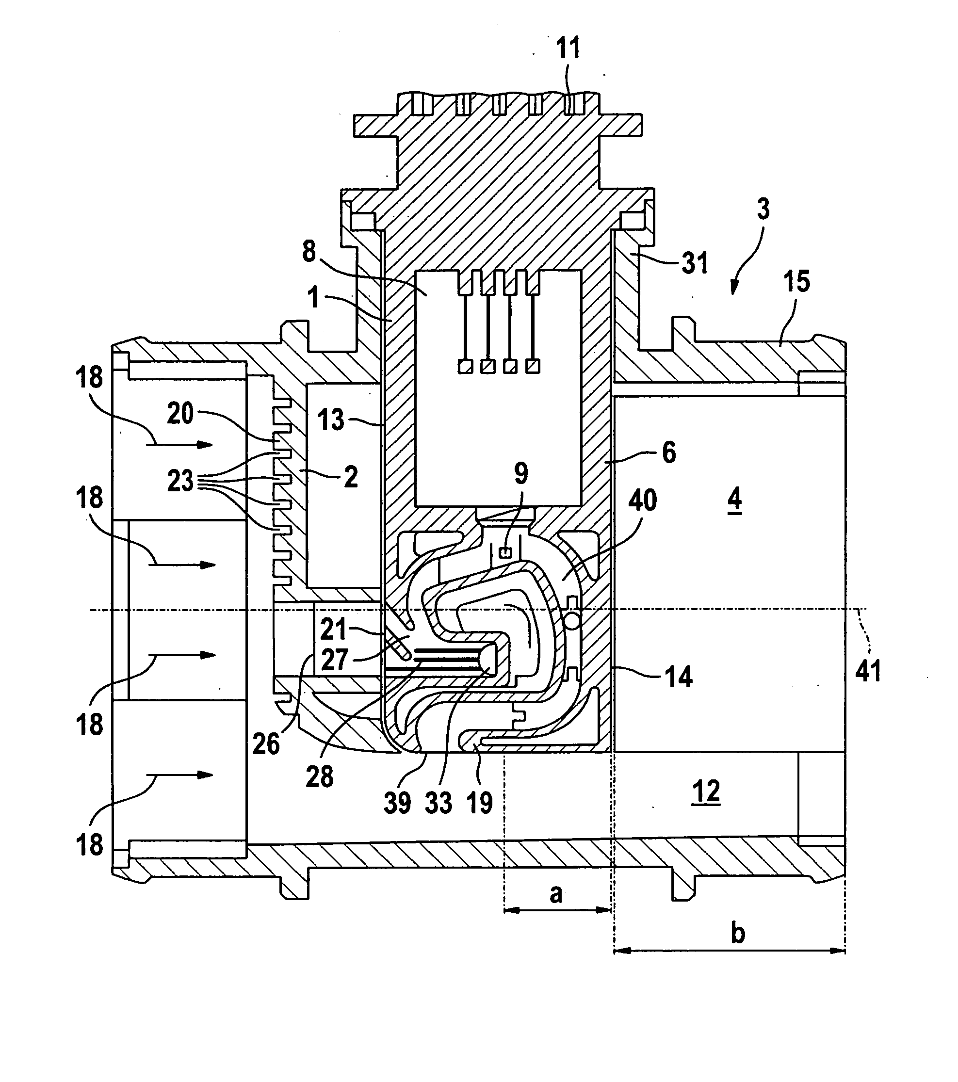
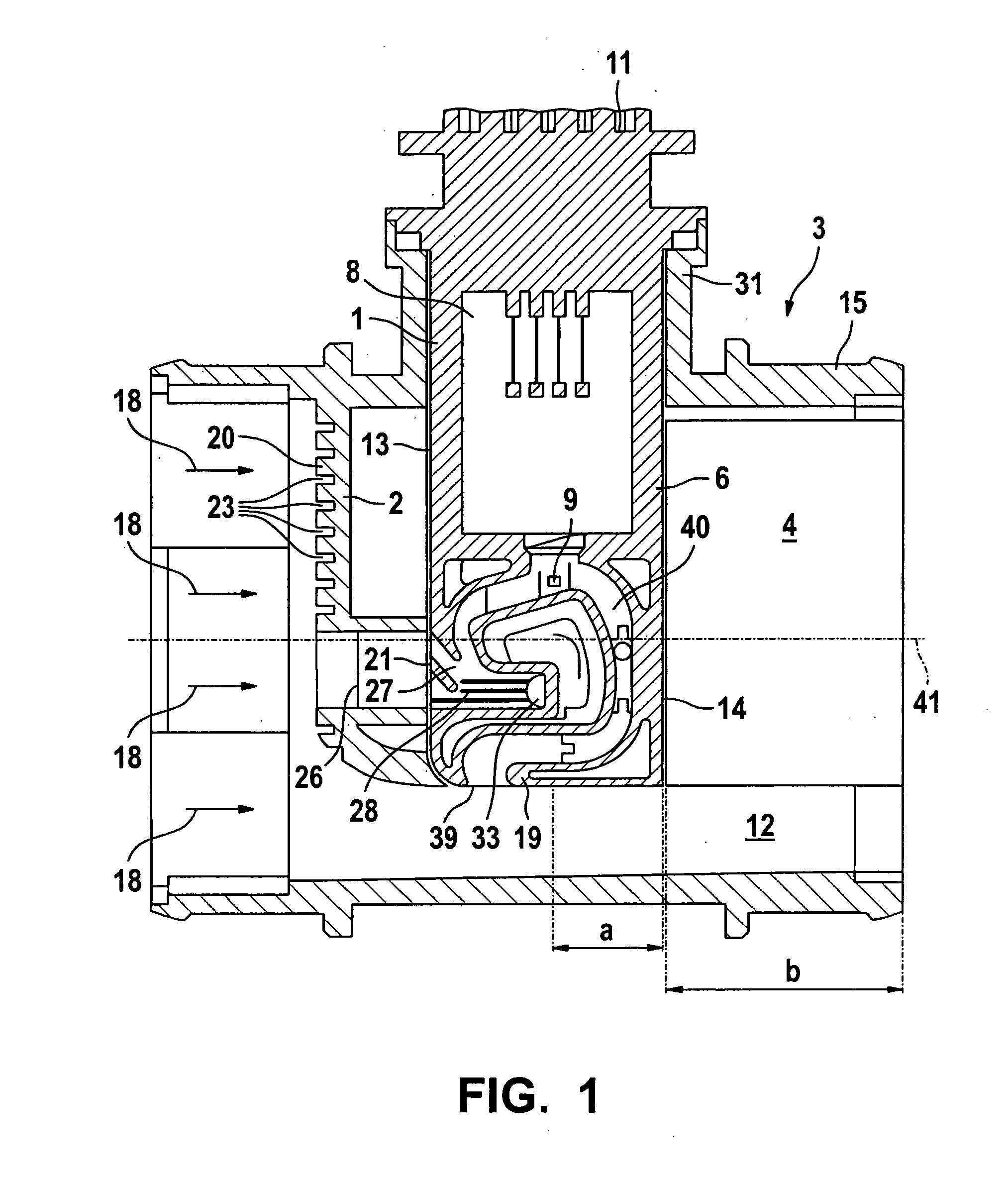
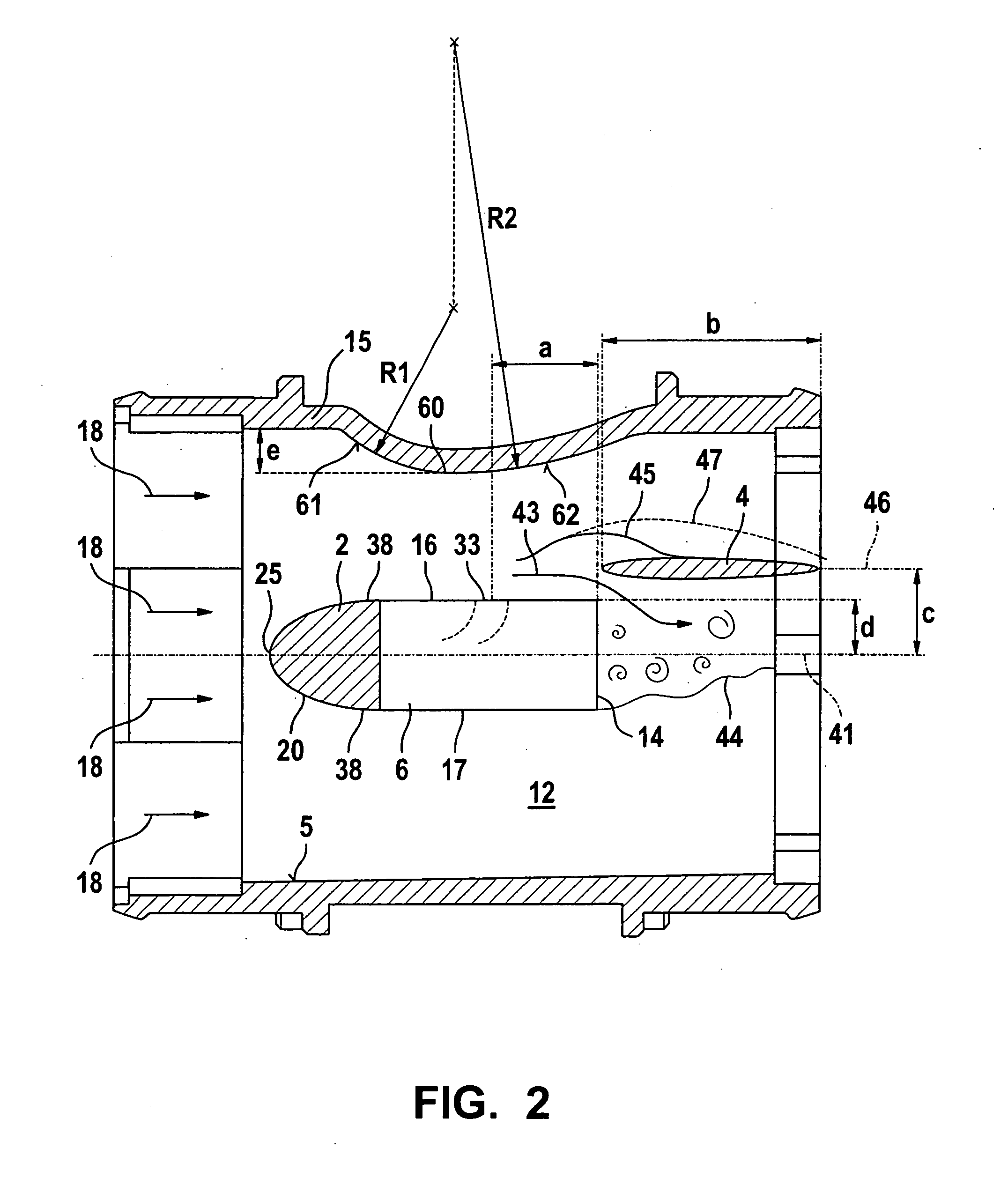
[0014]FIG. 1 shows a conduit part 3 having an approximately wall 15 in the form of a cylindrical jacket that surrounds a conduit passageway 12 in which a medium flows in a main flow direction. Conduit part 15 has a cylindrical inner wall 5. The main flow direction is indicated by corresponding arrows 18 in FIG. 1, running there from left to right. The main flow direction is defined as the direction in which the medium, beginning from the inlet of conduit part 3, flows to its outlet mainly through the conduit passageway, even if local eddy formations and local areas of separation of the flow exhibit local deviations of the flow from the main flow direction, or if temporary changes of direction occur. Here, the main flow direction runs parallel to mid-axis 41 of cylindrical jacket wall 15 of conduit part 3. Conduit part 3 can for example be situated in an intake conduit of an internal combustion engine. The medium can for example be air flowing to the internal combustion engine.

[0015...


PUM


Abstract

Devices are previously known for determining at least one parameter of a medium flowing in a conduit, in particular for determining the air mass flow in the intake section of an internal combustion engine, having a conduit part and a sensor device that has a bypass part. In order to avoid a flow detachment at the side walls of the bypass part, it is provided that a flow vane, running at least approximately parallel to a side wall, provided with a separation opening, of the bypass part, be provided in a conduit part behind a separation opening, seen in the main flow direction, and that the conduit part be provided, in the area of the bypass part, with at least one projection that protrudes from an inner wall of the conduit part towards the bypass part.

Description

BACKGROUND INFORMATION [0001] A device is described for example in German Patent Application No. DE 101 35 142, and is used for example in the intake section of an internal combustion engine to determine the air mass flow that is supplied to the internal combustion engine through a conduit. A segment, provided with a bypass part, of a sensor device is placed into the conduit part through a plug-in opening. The bypass part has a channel structure having an inlet area from which a measurement channel branches off that is provided with the measurement element. The inlet area additionally has a separation zone having at least one separation opening that opens into the conduit passageway at at least one side wall of the bypass part. The separation zone is used to separate out liquid and / or solid particles from the channel structure, so that they are prevented from entering the measurement channel provided with the measurement element and contaminating the measurement element. [0002] In t...

Claims


Application Information

Patent Timeline
IPC IPC(8): G01F1/68
CPCF02D41/18G01F1/684G01F15/12G01F1/72G01F5/00G01F1/6842
Inventor KONZELMANN, UWEGMELIN, CHRISTOPH
Owner ROBERT BOSCH GMBH
Why Eureka
Try Eureka