Robust barcode and reader for rod position determination

a barcode and reader technology, applied in the direction of hand-manipulated computer devices, instruments, electromagnetic radiation sensing, etc., can solve the problems of reducing processing power, requiring a relatively large amount of processing power to decode, and being used to determine the location of the rod

Inactive Publication Date: 2006-02-02
CATERPILLAR INC
View PDF30 Cites 12 Cited by
  • Summary
  • Abstract
  • Description
  • Claims
  • Application Information

AI Technical Summary

Benefits of technology

[0011] The processor circuit is configured to receive the sense signal, and determine a plurality of first probability values associated with the sense signal. Each of the plurality of first probability values being associated with first locations on the surface, and each of the first locations being spaced from one another by a first distance. The processor circuit selects groupings of the plurality of first probability values, a sum of which exceeding a first predetermined threshold. The processor circuit further being configured to determine a plurality of second probability values, each of which being associated with second locations on the surface. Each of the second locations being spaced from one another by a second distance less than the first distance, and each of the second locations lying within regions of the surface defined by the selected groupings.

Problems solved by technology

Such complex markings, however, typically require a relatively large amount of processing power to decode.
Although processing power may be reduced with a less complex code, such simpler codes have a limited number of permutations and thus can only be used to determine rod location over a limited range of distances.
Various non-idealities in the optics and electronics for sensing the barcode, however, as well as imperfections in the rod itself (e.g., spurious reflections on the rod surface and excess hydraulic fluid) can introduce noise into the sensor output signal.
Often, the amount of noise can be substantial, and the rod location difficult to determine.

Method used


Image

  • Robust barcode and reader for rod position determination
  • Robust barcode and reader for rod position determination
  • Robust barcode and reader for rod position determination

Examples


Embodiment Construction

[0035] Reference will now be made in detail to exemplary embodiments of the invention, examples of which are illustrated in the accompanying drawings. Wherever possible, the same reference numbers will be used throughout the drawings to refer to the same or like parts.

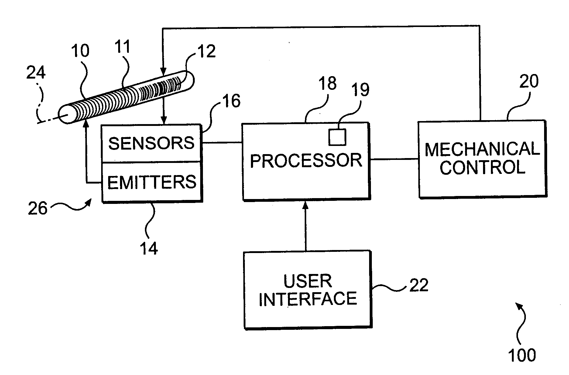
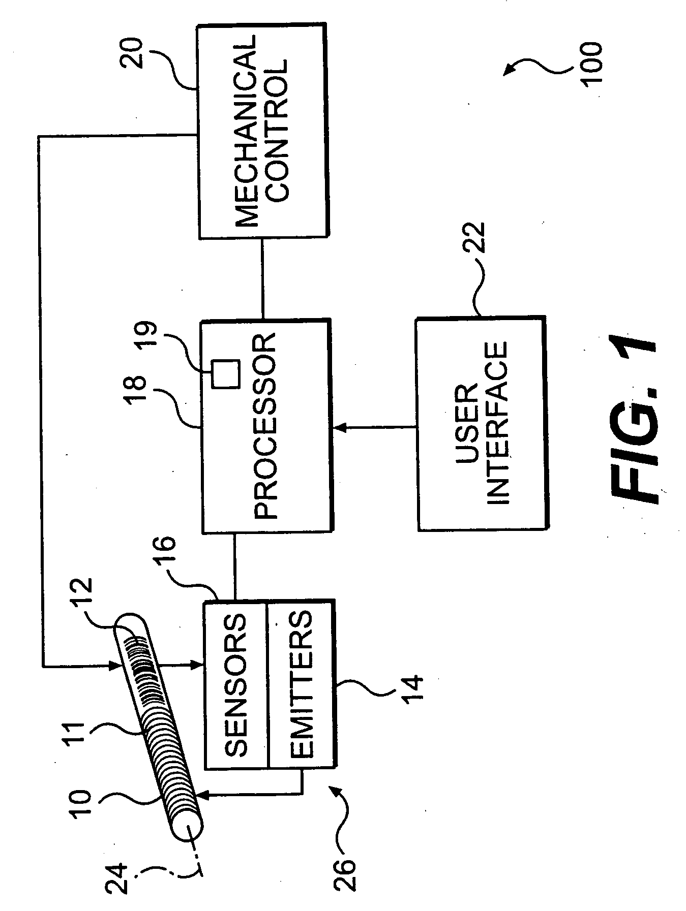
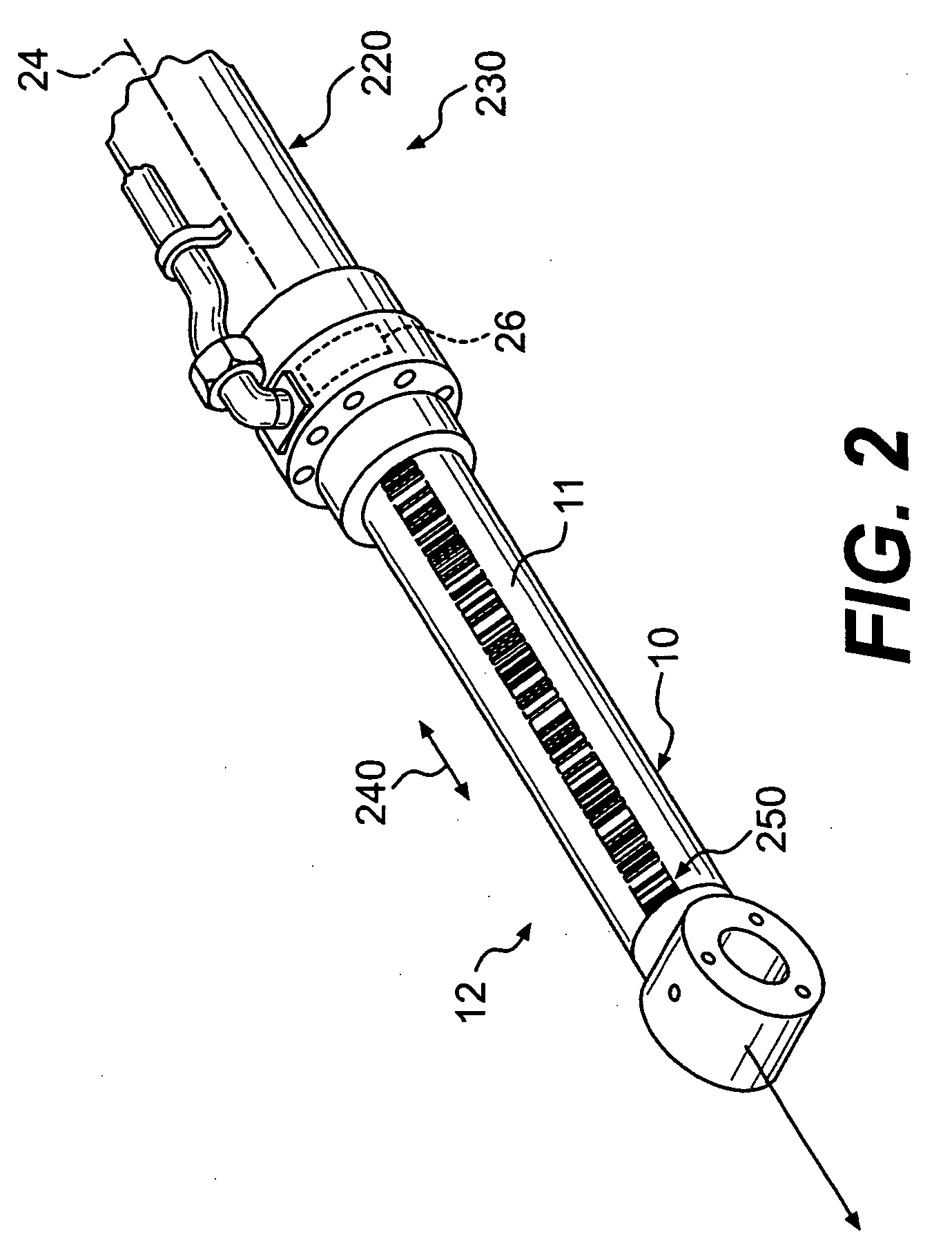
[0036]FIG. 1 illustrates a block diagram of system 100 for monitoring a position and controlling movement of movable member, object or rod 10. Rod 10 typically includes a conventional thermally sprayed outer surface 11 and a longitudinal axis 24. A plurality of markings 12 constituting a barcode are provided on outer surface 11, typically with a high intensity laser that selectively exposes portions of surface 11. Markings 12 represent binary coded information in the sense that the marks by being dark or light represent 0s or 1s (but this should not be confused with information about the position of the rod which is a more diffuse quantity). Reader circuit 26 includes one or more optical emitters 14, such as light emi...


PUM


Abstract

A barcode reader and processing circuitry are disclosed for identifying a position of a cylinder rod, for example, along a path of movement. The barcode is marked on a surface of the rod and constitutes a series of markings extending along a portion of the length of the rod. The markings represent encoded information based on numbers calculated with a random number generator, and are grouped into subsets, each of which corresponds to a particular rod position. A portion of the rod including a subset of barcode markings is exposed to light emitted from the reader. Light reflected off the barcode is sensed with an array of photosensors provided in the reader. The photosensors generate electrical signals, and using Bayesian probability, a likely subset of markings is determined corresponding to the received electrical signals. Once identified, the markings subset is associated with a location corresponding to the position of the rod. A barcode reader is also described that is relatively easy to assemble and provides uniform illumination of the barcode.

Description

TECHNICAL FIELD [0001] The present disclosure is directed generally to a system and related method for determining a location of a movable member, and more particularly, to determining the linear position of a movable member. BACKGROUND [0002] Many construction and earthmoving machines use a hydraulic or pneumatic cylinder for moving a work tool such as a bucket of a wheel loader or excavator. The cylinder includes a rod coupled to the work tool, at one end, and a chamber at the other. Hydraulic fluid is provided in the chamber to extend the rod along a linear path, typically extending several meters. The fluid can also be removed from the chamber to retract the rod along the same path. Often the rod location or position along the linear path must be known so that movement of the work tool can be controlled. [0003] Barcodes have been marked on cylinder rods in order to locate the position of the rod. In particular, the rod may be marked with a barcode including non-repeating segment...

Claims


Application Information

Patent Timeline
Patent Type & Authority Applications(United States)
IPC IPC(8): G06K7/10G06K19/06
CPCG06K7/10G06K7/10544G06Q20/203G06K19/06028G06K19/06
Inventor SEWELL, ROGER FANEJONES, ROBERT
Owner CATERPILLAR INC
Why Eureka
Try Eureka