Backlight unit

a backlight unit and backlight technology, applied in lighting and heating apparatus, lighting device details, instruments, etc., can solve the problems of lamp burnout or other inoperableness, complicated wiring of the related art backlight unit, and inability to meet the requirements of miniaturization and weigh

Active Publication Date: 2006-02-02
LG DISPLAY CO LTD
View PDF7 Cites 21 Cited by
  • Summary
  • Abstract
  • Description
  • Claims
  • Application Information

AI Technical Summary

Benefits of technology

[0027] Accordingly, the present invention is directed to a backlight unit that substantially eliminates one or more of the limitations or disadvantages of the related art.

Problems solved by technology

However, CRTs cannot satisfy demands for miniaturization and weight requirements due to their large size and relatively high weight.
These units are often operated for extended periods of time and often have long service lives, which often causes lamps to burn out or otherwise become inoperable.
Accordingly, the wiring of the related art backlight unit is very complicated.
Therefore, it is necessary to perform many additional steps to wire the unit, which lowers the manufacturing efficiency and the yield due to the increased number of manufacturing steps.
Accordingly, these steps lower the manufacturing efficiency and makes maintenance and repair of the light-emitting lamp more difficult and costly.
Accordingly, because the number of transformers corresponds to the number of light-emitting lamps, the production cost and the size of the backlight unit increases with the larger size of the LCD model.
As the size of the LCD device increases, the size of the unnecessary PCB portion increases with the addition of more light-emitting lamps and the increase in the length of the connection unit.
This additional size of the unnecessary PCB portion in the lower and upper parts increases the production cost and the size of the backlight unit.

Method used


Image

  • Backlight unit
  • Backlight unit
  • Backlight unit

Examples


Embodiment Construction

[0039] Reference will now be made in detail to the preferred embodiments of the present invention, examples of which are illustrated in the accompanying drawings. Wherever possible, the same reference numbers will be used throughout the drawings to refer to the same or like parts.

[0040] Hereinafter, a backlight unit according to the preferred embodiment of the present invention will be described with reference to the accompanying drawings.

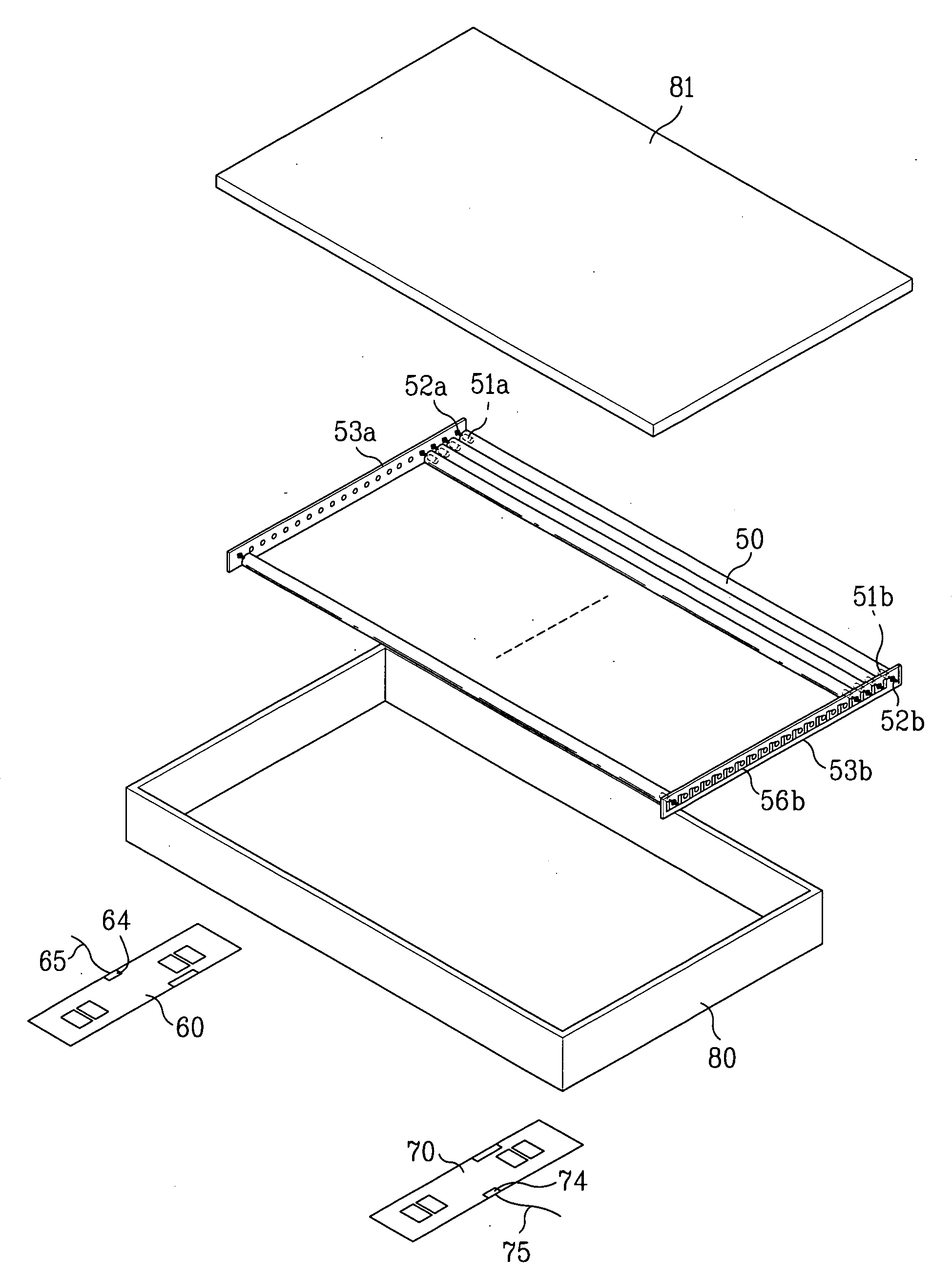
[0041]FIG. 5 is a perspective view of a backlight unit according to a preferred embodiment of the present invention. FIG. 6 is a plan view of the backlight unit of FIG. 5 showing a connection unit PCB and a driving unit PCB.

[0042] As shown in FIGS. 5 and 6, a backlight unit according to a preferred embodiment of the present invention includes a plurality of light-emitting lamps 50, first and second driving unit PCBs 60 and 70, and first and second connection unit PCBs 53a and 53b. As shown in FIG. 5, the plurality of light-emitting lamps 50 are ...


PUM


Abstract

A backlight unit is disclosed, to remove an unnecessary portion from a PCB and to decrease the number of connectors and wires, which includes a plurality of light-emitting lamps arranged in one direction inside a lamp housing; first and second driving unit PCBs positioned at both sides on the rear surface of the lamp housing, to apply a power to the light-emitting lamps; first and second connection PCBs positioned at both sides of the lamp housing, wherein the respective first and second connection PCBs are separately provided from the first and second driving unit PCBs; and first and second power supplying wires for the respective connection between the first and second driving unit PCBs with the first and second connection unit PCBs.

Description

[0001] This application claims the benefit of the Korean Application No. P2004-60234 filed on Jul. 30, 2004, which are hereby incorporated by reference. BACKGROUND OF THE INVENTION [0002] 1. Field of the Invention [0003] The present invention relates to a backlight unit, and more particularly, to a backlight unit to minimize the area of an inverter PCB and to decrease the number of connectors and power sources required for the backlight unit. [0004] 2. Discussion of the Related Art [0005] A cathode ray tube (CRT), a type of flat display device, has been widely used in various applications, including television monitors, measuring machines, and information terminals. However, CRTs cannot satisfy demands for miniaturization and weight requirements due to their large size and relatively high weight. Therefore, various types of alternative technologies have been successfully used as substitutes for CRTs including: liquid crystal displays (LCD), which use an electric field optical effect...

Claims


Application Information

Patent Timeline
Patent Type & Authority Applications(United States)
IPC IPC(8): F21V7/04
CPCG02F2001/133612G02F1/133604G02F1/133612G02F1/1335
Inventor AHN, IN HOLEE, JAE HOLEE, YONG KONLEE, TAE WOOK
Owner LG DISPLAY CO LTD
Why Eureka
Try Eureka