
Process for the preparation of a dealuminated zeolitic material having the bea framework structure

a technology of zeolitic material and framework structure, which is applied in the field of process for the preparation of a dealuminated zeolitic material having the framework structure, can solve the problems of high concentration of alumina, zeolite may be degraded, and the amount of removed al-species within one cycle may be too low,

Active Publication Date: 2018-01-25
BASF AG
View PDF5 Cites 10 Cited by
  • Summary
  • Abstract
  • Description
  • Claims
  • Application Information

AI Technical Summary

Benefits of technology

This invention describes a process for removing framework heteroatoms, such as aluminum, from a zeolitic material without causing instability. The process involves calcination in the absence of steam and acidic treatment to dissolve the aluminum. The resulting material has improved stability and can maintain its structure even at high temperatures. This is particularly surprising because other methods involving steaming can lead to damage of the framework structure. Overall, this process provides a highly stable and selective material suitable for use in catalytic conversion reactions.

Problems solved by technology

However, for various catalytic applications a high concentration of alumina is unfavorable.
If the parameters used in the dealumination process are not well adjusted, the zeolite may either be degraded during the process or the amount of removed Al-species within one cycle may be too low.
Despite the numerous existing methods for the dealumination of zeolitic materials, the problem nevertheless remains that both acid treatment and steaming at high temperatures of zeolite beta for its dealumination results in an instability of the zeolite framework due its chemical dissolution and the thermal strain it is exposed to, respectively.

Method used


Image

  • Process for the preparation of a dealuminated zeolitic material having the bea framework structure
  • Process for the preparation of a dealuminated zeolitic material having the bea framework structure
  • Process for the preparation of a dealuminated zeolitic material having the bea framework structure

Examples


reference example 1

Synthesis of Zeolite Beta

[0150]335.1 g of NaAlO2 were dissolved in 7314 g of H2O while stirring, followed by addition of 74.5 g of zeolite Beta seeds (commercially obtained from Zeolyst International, product name: CP814C. Prior to the synthesis, the product was calcined at 500° C. for 5 h (heating ramp 1° C. / min to obtain the H-Form)). The mixture was placed in a 20 L autoclave together with 7340 g sodium waterglass and 1436 g Ludox AS40, affording an aluminosilicate gel with a molar ratio of 1.00 SiO2:0.042 Al2O3:0.57 Na2O:17.5 H2O. Crystallization took place at 120° C. for 117 h. After the reaction mixture was cooled down to room temperature, the solid was separated by filtration, repeatedly washed with distilled water and then dried at 120° C. for 16 h affording 1337 g of a white crystalline product. Chemical analysis indicated an SiO2: Al2O3 molar ratio of 10.89 and 6.7 wt-% of Na2O on a calcined basis.

[0151]1000 g sodium form of the crystalline product was added into 10,000 g ...

reference example 2

ite Beta at 800° C. for 24 h

[0155]For calcination, the NH4-form of zeolite beta obtained in Reference Example 1 was taken as starting material. The white powder was heated in a muffle furnace with 3K / min to 800° C. under air. The temperature was held constant for 24 h. Afterwards, the sample was cooled down to room temperature. Chemical analysis indicated an Si / Al molar ratio of 5.0 and 2O on a calcined basis.

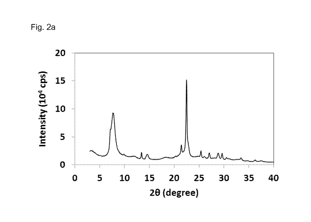
[0156]The X-ray diffraction pattern of the sample obtained is displayed in FIG. 2a. The BET surface area was measured by means of nitrogen sorption at 77K and afforded a value of 611 m2 / g. 27Al MAS NMR analysis (cf. FIG. 2b) revealed the following signal intensities in %: 50-60 ppm (Tetra-coordinated Al-sites) 45.3%, 15-45 ppm (Penta-coordinated Al-sites) 23.5%, −10-10 ppm (Hexa-coordinated Al-sites) 31.1%. The 29Si MAS NMR of the sample obtained is displayed in FIG. 2c and revels the following signal intensities in %: −102 ppm (Q4 (1Al)+Q3) 26%, 15-108 ppm (Q4 (0Al, T3-T9)) 61...

reference example 3

ite Beta at 750° C. for 15 h

[0157]For calcination, the NH4-form of zeolite beta obtained in Reference Example 1 was taken as starting material. The white powder was heated in a muffle furnace with 3K / min to 750° C. under air. The temperature was held constant for 15 h. Afterwards, the sample was cooled down to room temperature. Chemical analysis indicated a Si / Al ratio of 5.0 and 2O on a calcined basis. The BET surface area was measured by means of nitrogen sorption at 77K affording a value of 604 m2 / g.

[0158]The X-ray diffraction pattern of the sample obtained is displayed in FIG. 3a, and displays the following reflections and corresponding intensities:

AngleIntensity[2-Theta °][%]3.3912.26.603127.13434.37.69450.89.81711.711.7828.713.34613.413.577.414.50810.518.2028.120.1549.521.34522.121.70314.322.410022.64127.124.4359.224.7629.425.2971625.9661026.94814.427.93828.64313.629.29734.729.53614.230.4138.130.836.932.465633.3588.236.1245.6

[0159]27Al MAS NMR analysis (see FIG. 3b) revealed t...


PUM

PropertyMeasurementUnit
Temperatureaaaaaaaaaa

Abstract

The present invention relates to a method for the preparation of a treated zeolitic material having a BEA framework structure comprising the steps of: (i) providing a zeolitic material having a BEA framework structure, wherein the BEA framework structure comprises YO2 and X2O3, wherein Y is a tetravalent element, and X is a trivalent element, and wherein the zeolitic material having a BEA framework structure is obtainable and / or obtained from an organotemplate-free synthetic process; (ii) calcining the zeolitic material provided in step (i) at a temperature of 650° C. or more; and (iii) treating the calcined zeolitic material obtained from step (ii) with an aqueous solution having a pH of 5 or less, as well as to zeolitic materials per se preferably obtainable according to the inventive method and to their use, and to a process for converting oxygenates to olefins employing the inventive zeolitic materials.

Description

[0001]The present invention relates to a method for the preparation of a dealuminated zeolitic material having a BEA framework structure. Furthermore, the present invention relates to a zeolitic material as obtained or as obtainable according to the inventive process, as well as to a zeolitic material per se having a BEA framework structure and displaying the specific characteristics as found in the dealuminated zeolitic materials obtained according to the inventive method. Finally, the present invention relates to a process for the conversion of oxygenates to olefins employing the inventive zeolitic materials having a BEA framework structure as well as to the use of said materials in general, and in particular as a catalyst for the conversion of organic compounds.INTRODUCTION[0002]The most prominent and best studied example for a zeolitic material with a BEA framework structure is zeolite Beta, which is a zeolite containing SiO2 and Al2O3 in its framework and is considered to be on...

Claims


Application Information

Patent Timeline
IPC IPC(8): C01B39/02B01J29/70C07C1/20C01B39/46
CPCC01B39/026C01B39/46B01J29/7007C07C1/20C07C2529/70B01J2229/37B01J2229/36B01J2229/40B01J35/30C07C11/02C01P2002/86
Inventor FEYEN, MATHIASMAURER, STEFANMUELLER, ULRICHBAO, XINHEZHANG, WEIPINGDE VOS, DIRKGIES, HERMANNXIAO, FENG-SHOUTOSHIYUKI, YOKOIYILMAZ, BILGEOTOMO, RYOICHI
Owner BASF AG
Learn More