Inkjet printhead with ink supply passage formed from both sides of the wafer by overlapping etches

a technology of inkjet printheads and wafers, which is applied in the direction of recording equipment, instruments, and recording information storage, etc., can solve the problems of difficult and time-consuming stripping of resist 200-micron depth passages, inability to form ink supply passages, and difficulty in forming ink supply passages from the supply side of the wafer to the nozzle sid

Inactive Publication Date: 2005-11-08
MEMJET TECH LTD +1
View PDF8 Cites 8 Cited by
  • Summary
  • Abstract
  • Description
  • Claims
  • Application Information

AI Technical Summary

Benefits of technology

[0063]Each active fluid-ejecting structure and each static fluid-ejecting structure may be shaped so that, when fluid is received in the nozzle chamber, the fluid-ejecting structures and the fluid define a fluidic seal to inhibit fluid from leaking out of the nozzle chamber between the fluid-ejecting structures.

Problems solved by technology

As set out in the above referenced applications / patents, the Applicant has spent a substantial amount of time and effort in developing printheads that incorporate micro electro-mechanical system (MEMS)—based components to achieve the ejection of ink necessary for printing.
It is not practical to form the ink supply passages from the nozzle side of the wafer through to the supply side.
To strip a 200-micron deep passage of resist would be difficult and time consuming.
Forming the ink supply passages from the supply side of the wafer through to the nozzle side presents its own difficulties.
Firstly, the precise alignment of the masking on the supply side with the ink chambers of each nozzle on the other side is difficult.
Secondly, a deep etch will often deviate from a straight path because the ions in the etchant are influenced by any charged particles in the wafer.
Thirdly, the plasma etchant will often track sideways along an interface between silicon wafer and dielectric material.
Misalignment of the supply passage can lead to the plasma etch contacting and damaging other components of the nozzle, for example, the drive circuitry for the ejection actuator.
Furthermore, the above causes of misalignment can compound into large inaccuracies which imposes limits on the size of the nozzle structure and the spacing between nozzles.
This, of course, reduces the density of nozzles and lowers the resolution.

Method used


Image

  • Inkjet printhead with ink supply passage formed from both sides of the wafer by overlapping etches
  • Inkjet printhead with ink supply passage formed from both sides of the wafer by overlapping etches
  • Inkjet printhead with ink supply passage formed from both sides of the wafer by overlapping etches

Examples


Embodiment Construction

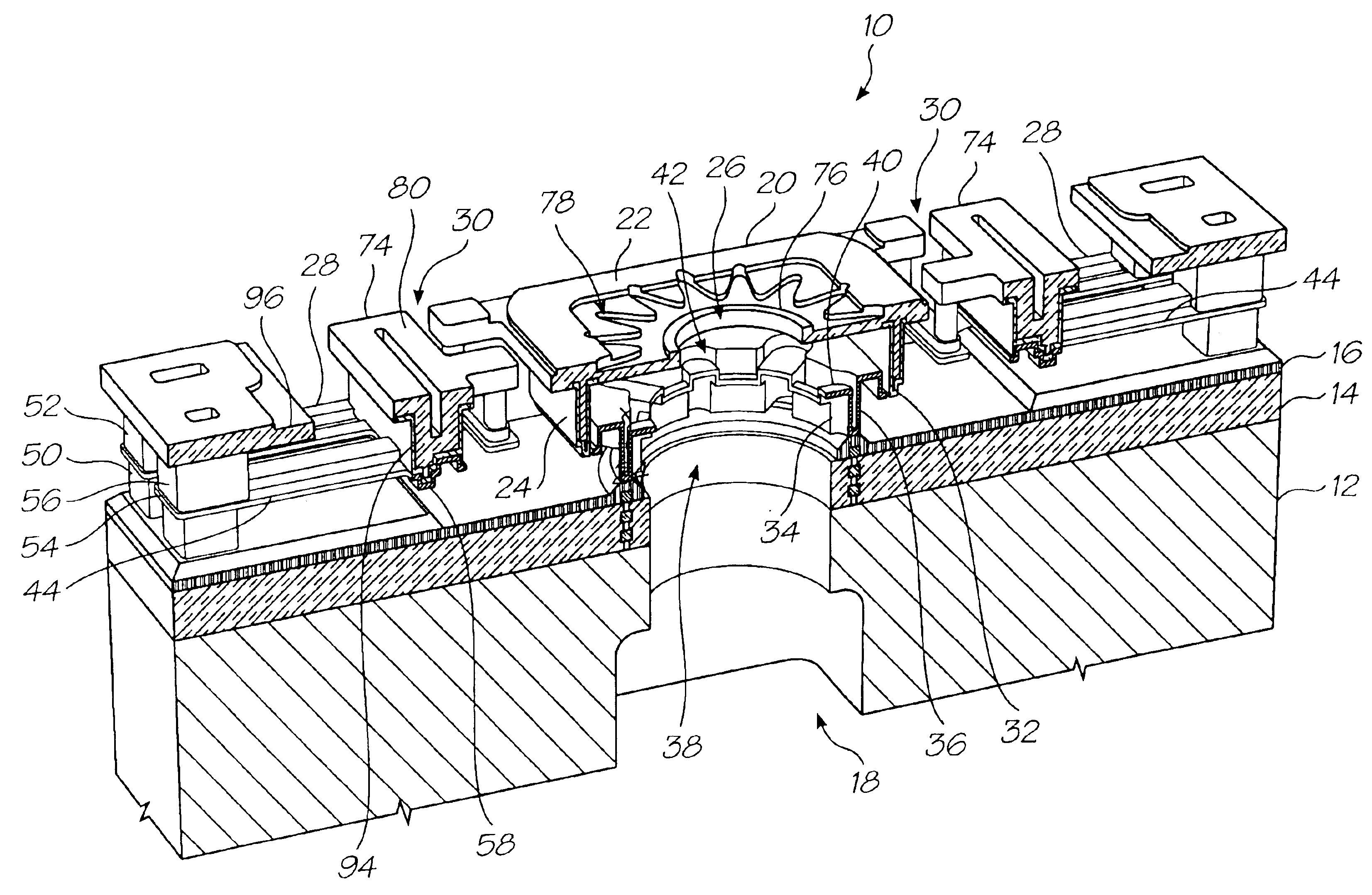
[0087]The present invention is applicable to printheads formed on and through silicon wafers by lithographic etching and deposition techniques, regardless of whether bubble forming heater elements or thermal bend actuators are used.

[0088]Bubble Forming Heater Element Actuated Printheads

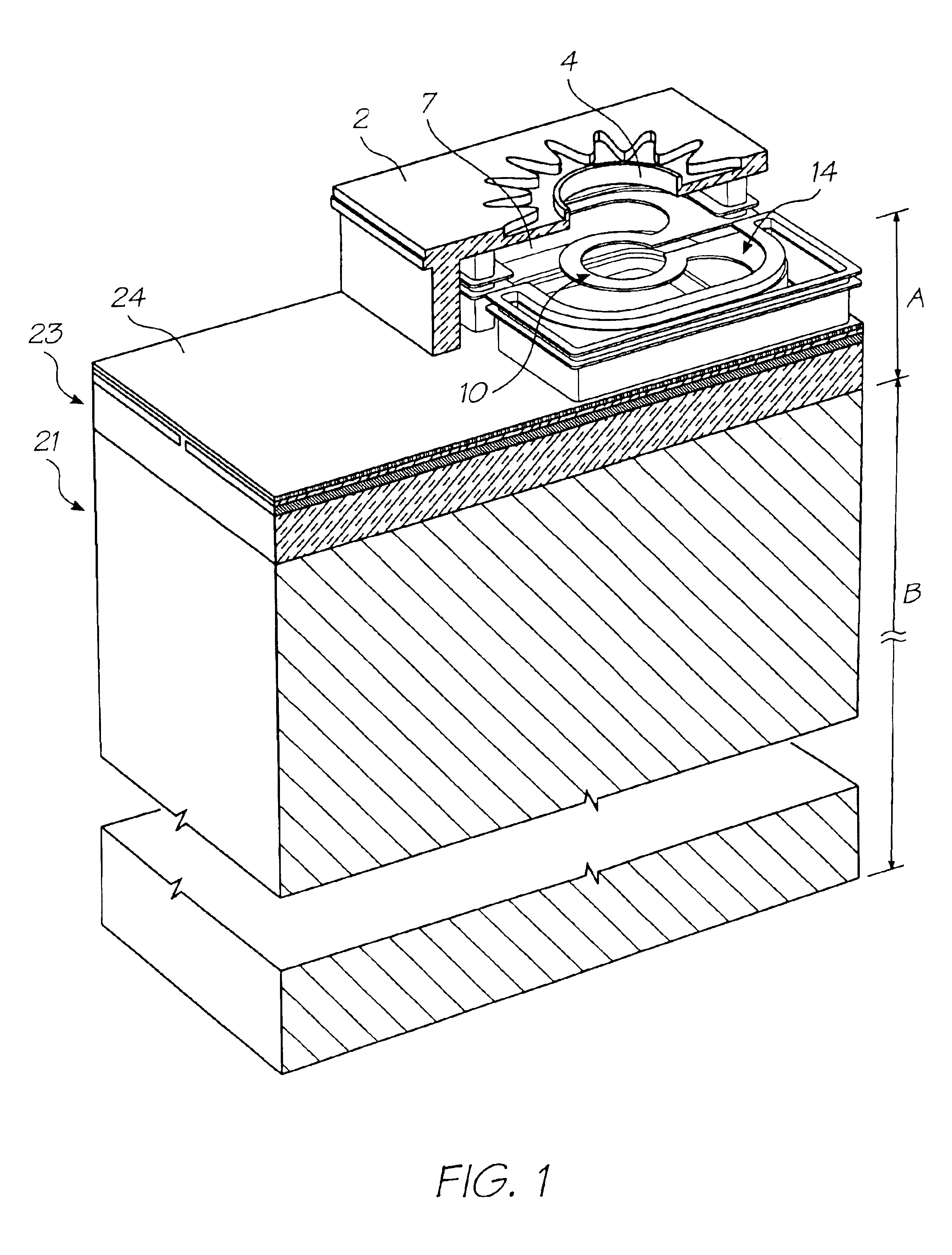
[0089]FIG. 1 shows a nozzle of this type. The nozzles, ejection actuators, associated drive circuitry and ink supply passages are formed on and through a wafer using lithographically masked etching techniques described in great detail in U.S. Ser. No. 10 / 302,274. In the interests of brevity, the disclosure of the '274 application is incorporated herein in its entirety. For convenience, the reference numerals on FIGS. 1 to 7 accord with the reference numbering used in '274. Corresponding features of the embodiments shown in FIGS. 8 to 20 do not necessarily use the same reference numerals.

[0090]The unit cell 1 is shown with part of the walls 6 and nozzle plate 2 cut-away, which reveals the interior of t...


PUM

PropertyMeasurementUnit
widthaaaaaaaaaa
widthaaaaaaaaaa
thickaaaaaaaaaa

Abstract

An inkjet printhead with nozzles 4 and liquid passages 31, 32 leading to each nozzle. The nozzles, ejection actuators 14, associated drive circuitry 22 and liquid passage 31, 32 being formed on and through a wafer 21 using lithographically masked etching technique, such that the wafer has a droplet ejection side and a liquid supply side. Each of the liquid passages is formed by etching a hole 31 partially through the wafer 21 from the droplet ejection side, and etching a passage from the liquid supply side of the wafer 21 to the hole 31. Etching a hole 31 into the wafer 21 from the droplet ejection side means the ink supply passage 32 can stop short of the interface between the dielectric 23 and the wafer 21 to prevent the etchant from tracking sideways and damaging the drive circuitry 22. As the inlet hole 31 is relatively shallow, the removal of the resist is not overly difficult. However, setting the depth of the supply passage etch so that it overlaps the blind end of the hole by more than the combined tolerances of both etching processes ensures an adequate fluid connection to the nozzle. This permits a more compact overall design and higher nozzle packing density.

Description

CROSS REFERENCE TO RELATED APPLICATIONS[0001]This application is a continuation-in-part of U.S. application Ser. No. 10 / 307 / 330 filed on Dec. 2, 2002, now issued U.S. Pat. No. 6,666,544, which is a continuation application of U.S. application Ser. No. 10 / 120,439 filed on Apr. 12, 2002, now issued U.S. Pat. No. 6,536,874.STATEMENT REGARDING FEDERALLY SPONSORED RESEARCH OR DEVELOPMENT[0002]Not ApplicableFIELD OF THE INVENTION[0003]This invention relates to the fabrication of fluid ejection chips. More particularly, this invention relates to fabrication techniques of fluid ejection chips that minimize the spacing between adjacent nozzles.REFERENCED PATENT APPLICATIONS[0004]The following applications are incorporated by reference:[0005]6,227,6526,213,5886,213,5896,231,1636,247,79509 / 113,0996,244,6916,257,70409 / 112,7786,220,6946,257,7056,247,7946,234,6106,247,7936,264,3066,241,3426,247,7926,264,3076,254,2206,234,61109 / 112,80809 / 112,8096,239,82109 / 113,0836,247,79609 / 113,12209 / 112,79309 / 11...

Claims


Application Information

Patent Timeline
Patent Type & Authority Patents(United States)
IPC IPC(8): B41J2/14B41J2/16B41J2/175
CPCB41J2/14B41J2/1412B41J2/14427B41J2/16B41J2/1601B41J2/1626B41J2/1631B41J2/1635B41J2/1639B41J2/1648B41J2/1628Y10T29/49401B41J2002/14435
Inventor SILVERBROOK, KIA
Owner MEMJET TECH LTD
Why Eureka
Try Eureka